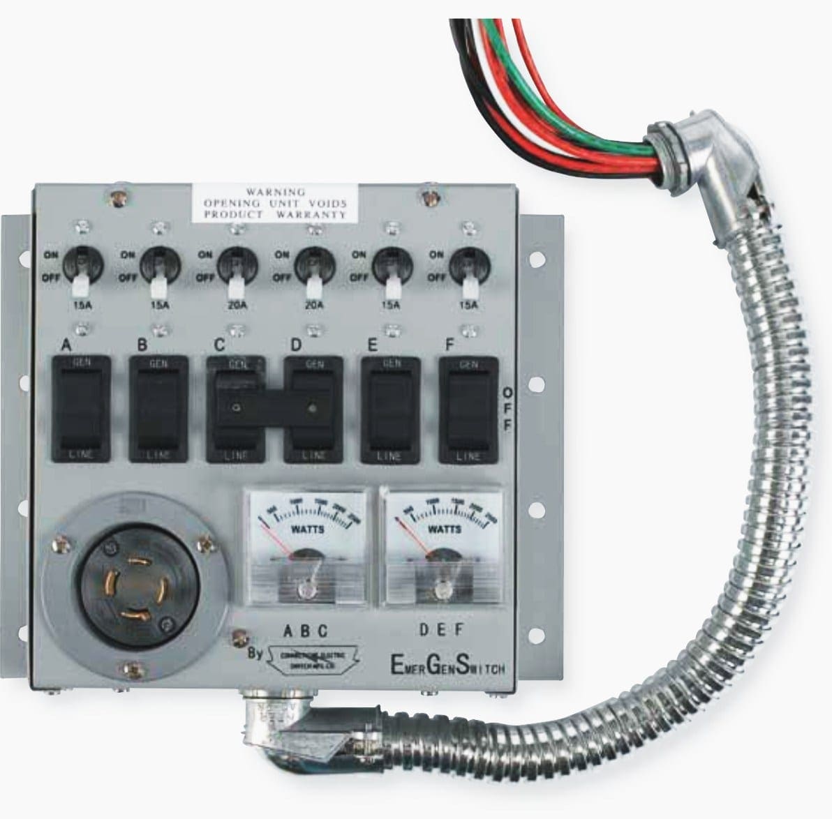
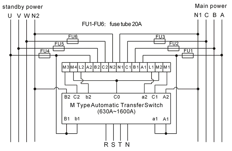
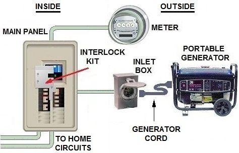
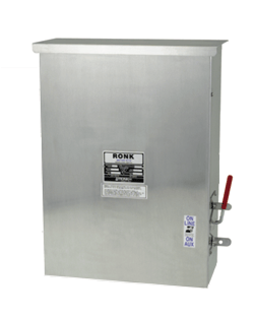
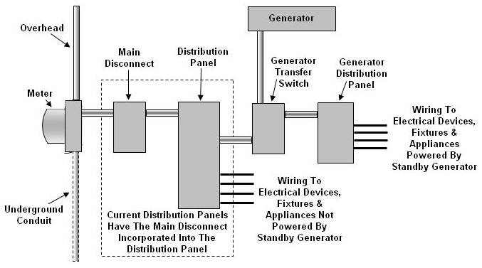
Manual transfer switches require an operator to change the power source while automatic switches detect the loss of power start the back up generator and switch over to the backup power feed. Assortment of generac manual transfer switch wiring diagram.

How To Use A Manual Transfer Switch System For Your Home Ac
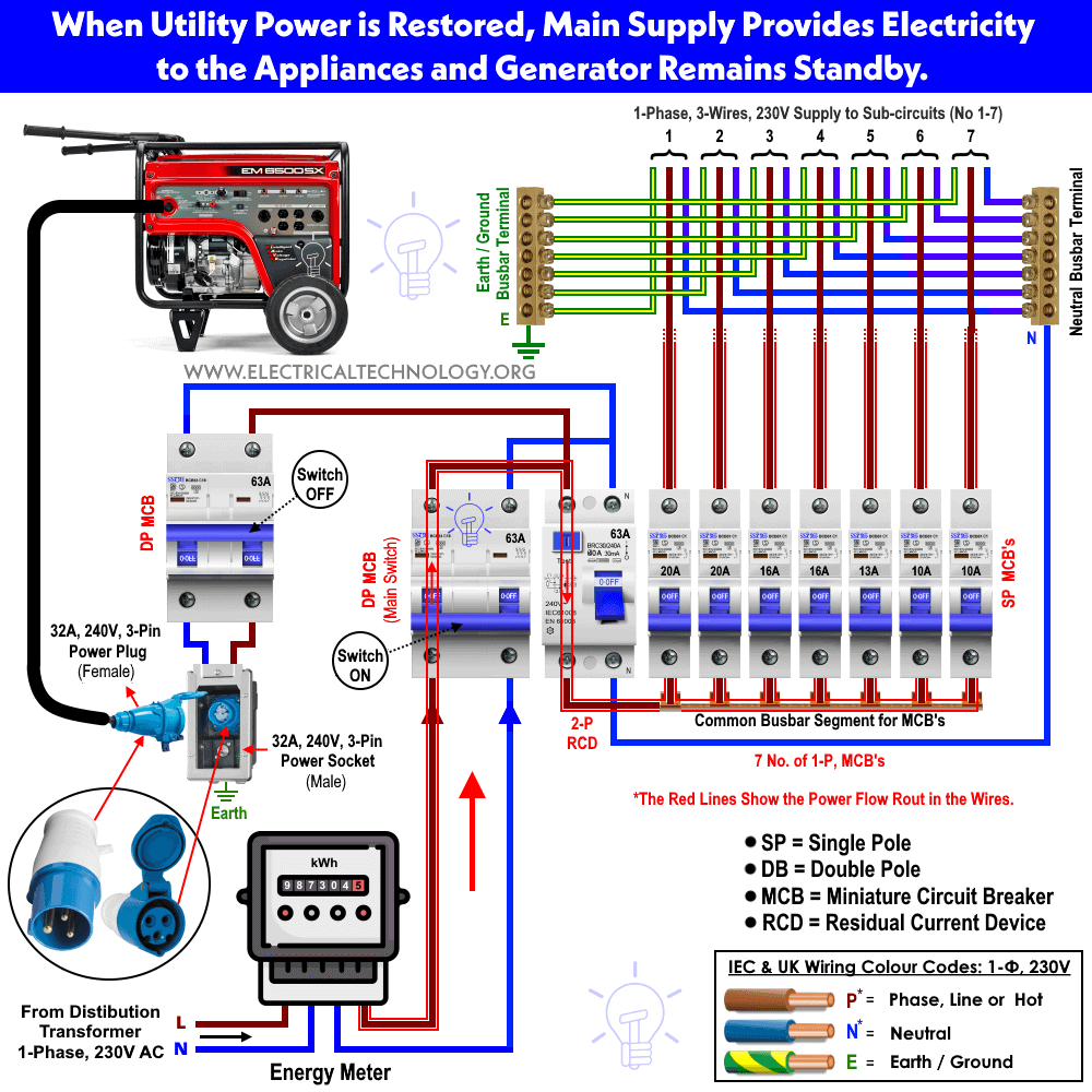
Manual transfer switch wiring diagram. The wires should be drawn through 1 of 3 knockouts located on the underside of the switch. When utility power is functioning the wires from the circuit breaker in the main electrical distribution panel are connected to the generator sub panel. It is also shows the working and operation for different changeover switches wiring connections like single phase manual changeover switch with generator three phase manual transfer switch connection with generator as well as single phase and three phase automatic transfer switches connections to the 1 and 3 phase generators and main fuse board. A wiring diagram is a simplified conventional pictorial depiction of an electrical circuit. Electrical manual changeover switch wiring diagram for portable generator manual changeover switch are mostly use in 2 types in which one have the move able knob and 2nd one the handle changeover switch. From outside drill a 1½ inch diameter hole through the house wall.
They should join the circuit breaker through a knockout found at the bottom of the box. It reveals the elements of the circuit as streamlined shapes and the power and also signal connections in between the gadgets. Use the transfer switchs wiring harness to connect the unit to the circuit breaker. It reveals the components of the circuit as streamlined forms and also the power as well as signal connections in between the gadgets. If utility power fails the switch connects the generators power to the circuits in the generator sub panel. It shows the elements of the circuit as simplified shapes and also the power and also signal links between the devices.
A wiring diagram is a simplified traditional pictorial representation of an electrical circuit. Variety of manual transfer switch wiring diagram. Variety of reliance transfer switch wiring diagram. This post i will shown the complete method of manual or handle change over switch the knob type manual changeover switch wiring same like. It reveals the parts of the circuit as simplified shapes as well as the power and also signal links between the devices. Mount the transfer switch to wall beside the existing main electrical panel.
A wiring diagram is a streamlined standard pictorial representation of an electrical circuit. Because the amount of electricity created by a backup generator is not adequate to power all of the electrical circuits in your house youll need to designate a few selected circuits to get backup. Figure 5 wiring diagram of a manual transfer switch in the on position. A wiring diagram is a simplified traditional pictorial depiction of an electric circuit. Turn off the power to the house at the main electrical panel and connect the wires coming from the transfer switch to the breakers in the main panel. Assortment of manual transfer switch wiring diagram.
