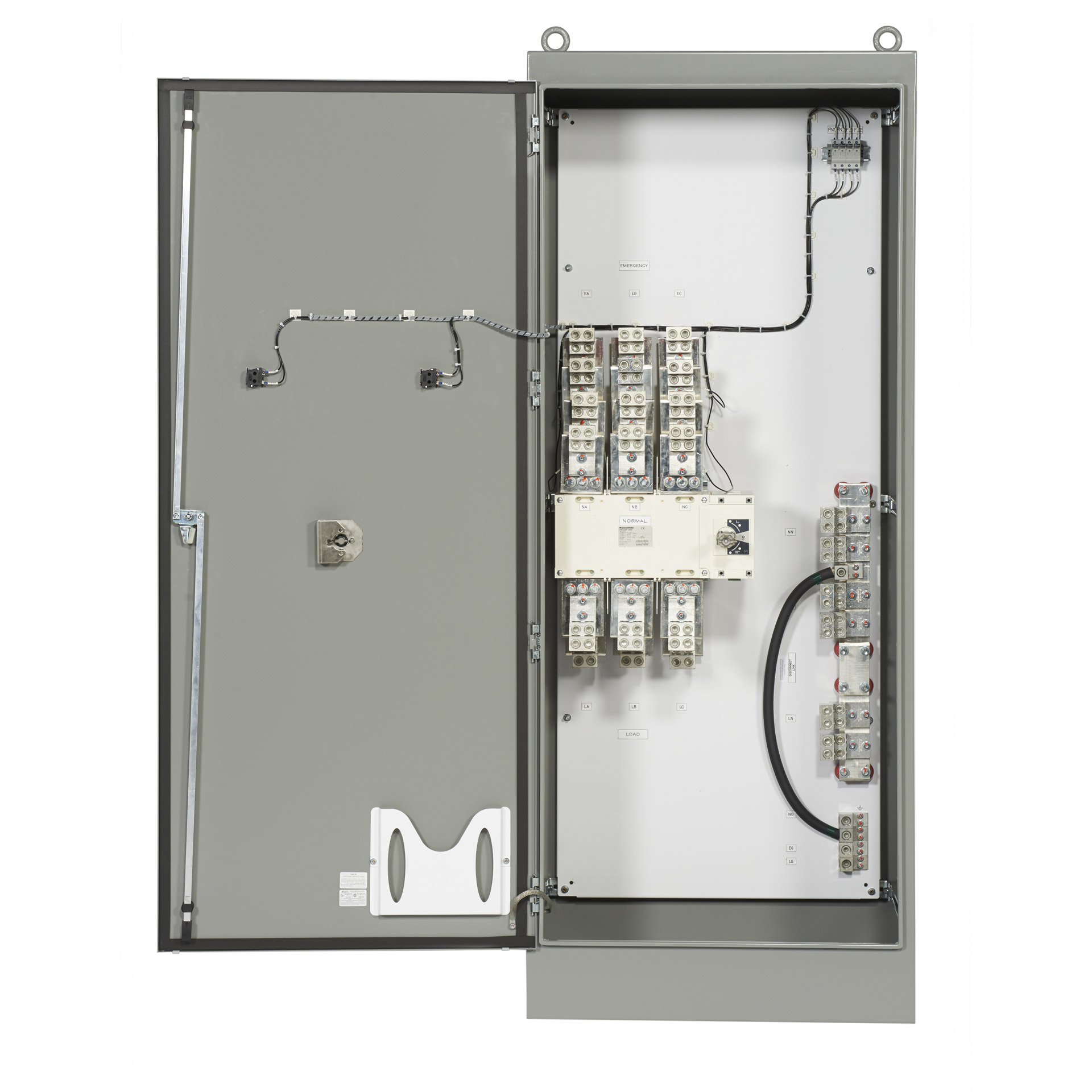
Generac manual transfer switch wiring diagram sources. Generac 200 amp automatic transfer switch wiring diagram whole house transfer switch wiring diagram fresh generac 200 automatic transfer switch wiring diagram 973 file type.
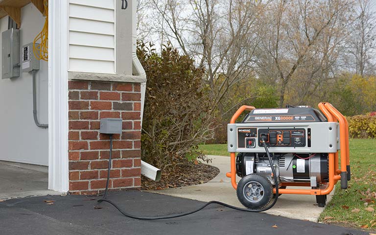
Planning A Manual Transfer Switch Installation Materials
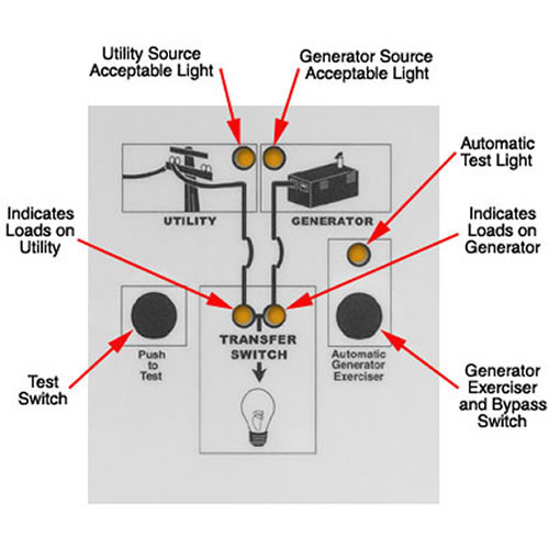
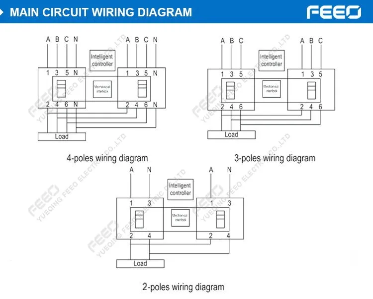
200 amp manual transfer switch wiring diagram. 100 amp 200 amp spec sheet. The wires should be drawn through 1 of 3 knockouts located on the underside of the switch. Use the transfer switchs wiring harness to connect the unit to the circuit breaker. This ul listed transfer switch is for use in optional standby sys tems only nec article 702. A wiring diagram is a simplified traditional pictorial depiction of an electrical circuit. It shows how a electrical wires are interconnected which enable it to also show where fixtures and components might be connected to.
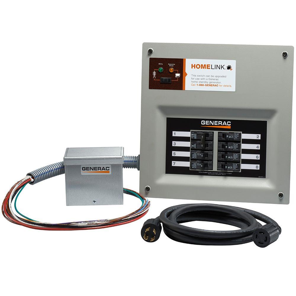
Generac now offers added flexibility by combining the load center and transfer switch in a single panel. It reveals the components of the circuit as simplified forms and also the power and signal links between the gadgets. Amp service entrancenon service entrance automatic transfer switch owners manual. Variety of 200 amp automatic transfer switch wiring diagram. Generac 400 amp transfer switch wiring diagram download. Generac 200 amp transfer switch wiring diagram what is a wiring diagram.
Refer to the smm ownersinstallation manual forvariety of generac amp automatic transfer switch wiring diagram. They should join the circuit breaker through a knockout found at the bottom of the box. Switch and the tungsten load does not exceed 30 percent of the switch rating. Whole house transfer switch wiring diagram beautiful generator. Generac 200 amp transfer switch wiring diagram collections of generac 200 amp automatic transfer switch wiring diagram sample. For use with 6 250 awgkcmil copper or aluminum lug wire this transfer switch is rated for safety with a ul listing and an ansi certification.
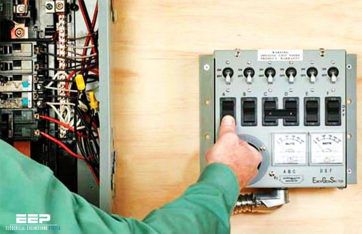
This emergency power transfer switch offers a nema type 3r metal enclosure for outdoor use. Manual transfer switches require an operator to change the power source while automatic switches detect the loss of power start the back up generator and switch over to the backup power feed. Run your backup generator with the ge 200 amp 240 volt non fused emergency power transfer switch. This provides our customers with a more efficient installation and cost effective solution for new home construction or service upgrades. A wiring diagram is a simplified conventional photographic representation of an electric circuit. Because the amount of electricity created by a backup generator is not adequate to power all of the electrical circuits in your house youll need to designate a few selected circuits to get backup.
This transfer switch is suitable for use on a circuit capable of 22000 rms 200a and 10000 100a symmetrical amperes 240 vac maximum. A wiring diagram is a simple visual representation from the physical connections and physical layout of the electrical system or circuit.


