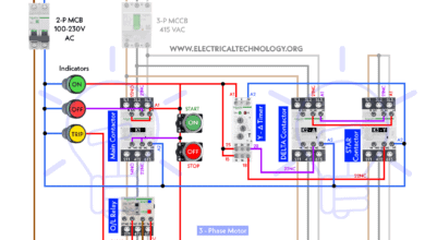
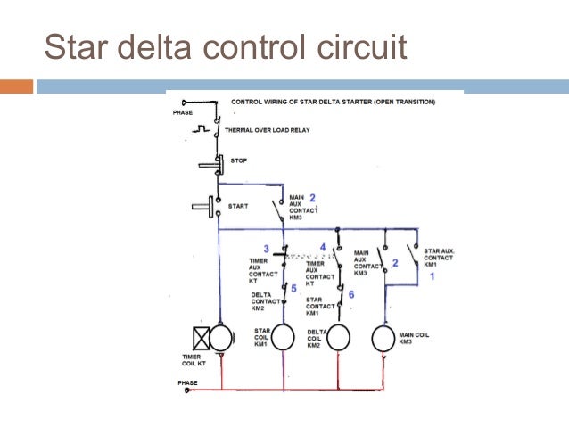
The on delay timer diagram is also shown in the diagram. The control circuit uses to control the starter circuit such as on off and tripping operations.

Star Delta Starter Control Wiring Diagram With Timer Filetype
Star delta wiring diagram with timer pdf. The power circuit uses to create contact between the motor and three phase power supply. Now lets see the star delta starter control circuit diagram with timer ncno push button switches. A dual starter connects the motor terminals directly to the power supplyhence the motor is subjected to the full voltage of the power supplyconsequently high starting current flows through the motor. What i have given in this wiring diagram the same will be used in many industrial. Star delta starters consist of a power circuit and control circuit. The star delta wye delta starting method controls whether the lead connections from the motor are configured in a star or delta electrical connection.
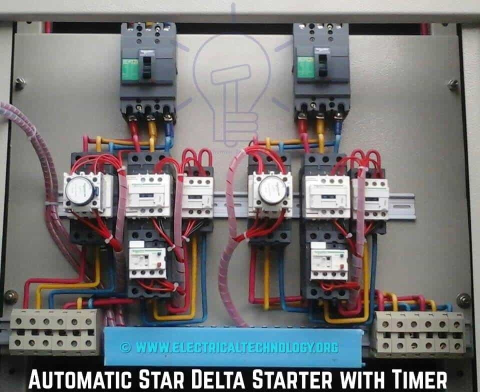
Refer to the below star delta circuit. Star delta connection circuit diagram. This type of starting is suitable for small motors below 5 hp 375 kw. A 8 pin timer are used. Star delta wiring diagram electrical engineering updates. Here will see the practical star delta starter wiring diagram.
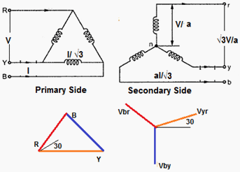
In this tutorial we will show the star delta y δ 3 phase induction ac motor starting method by automatic star delta starter with timer with schematic power control and wiring diagram as well as how star delta starter works and their applications with advantages and disadvantages. Star delta starter control circuit diagram. The initial connection should be in the star pattern that results in a reduction of the line voltage by a factor of 13 577 to the motor and the current is reduced. Star delta connection diagram and working principle. The above is a star delta starter wiring diagram 3 phase motor for main wiring.


