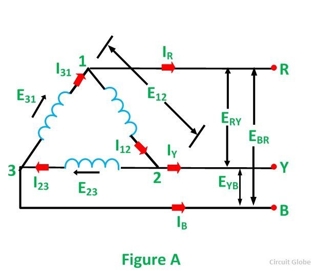
Vry vrn. Star connection line and phase currents.

Phasor Diagram And Phasor Algebra Used In Ac Circuits
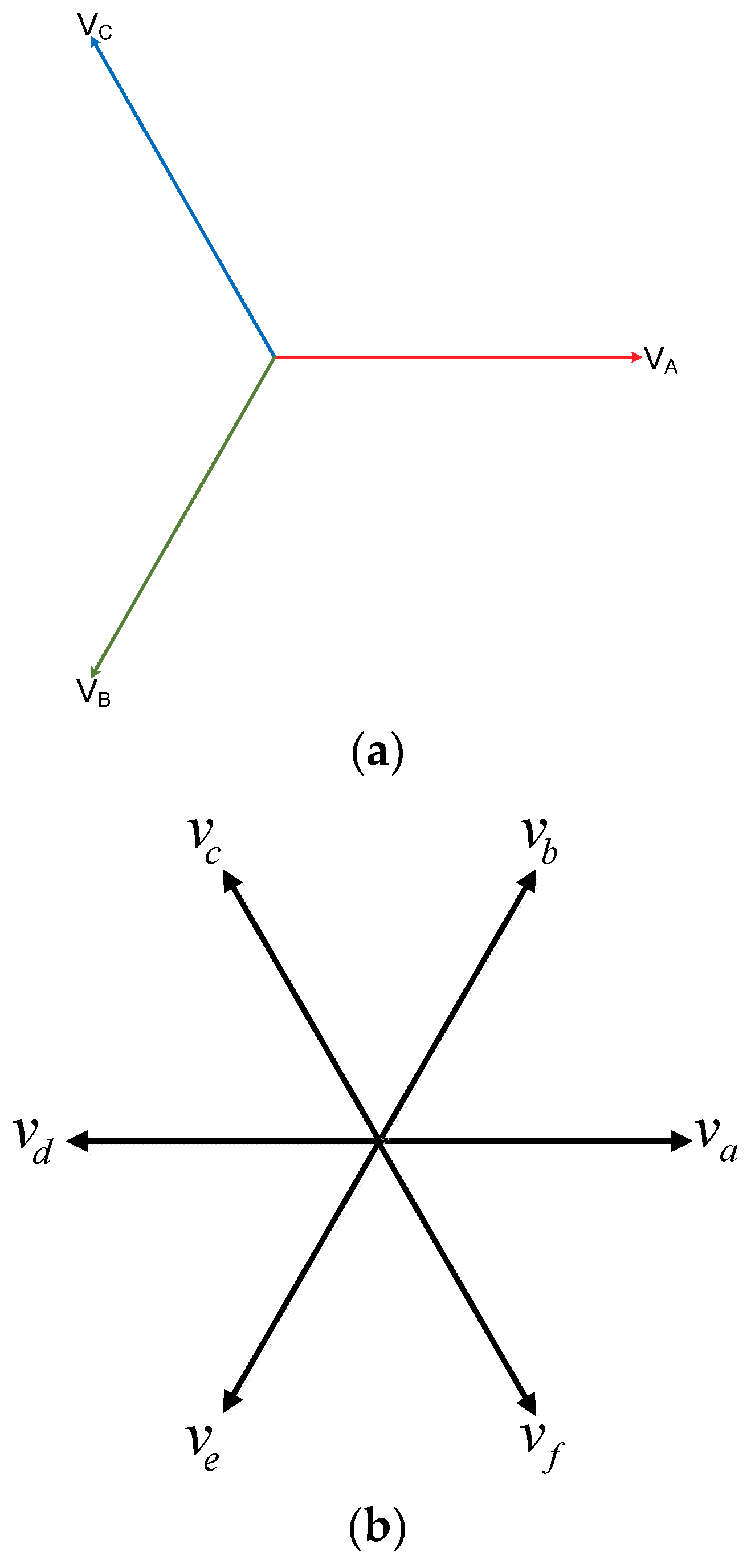
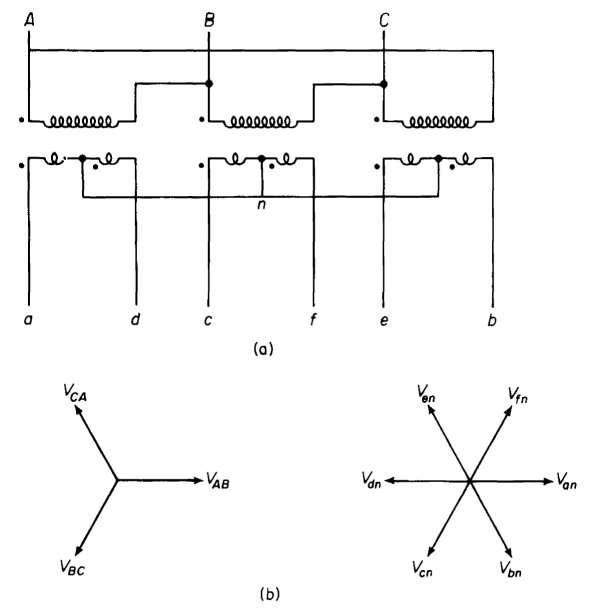
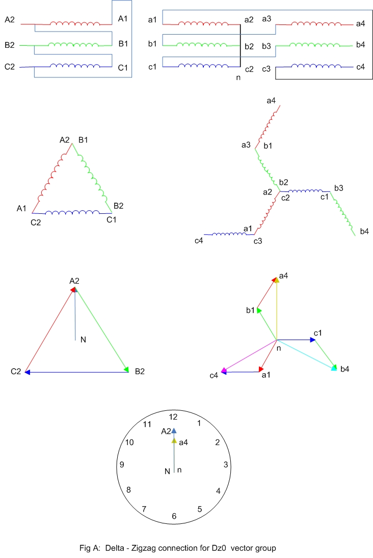
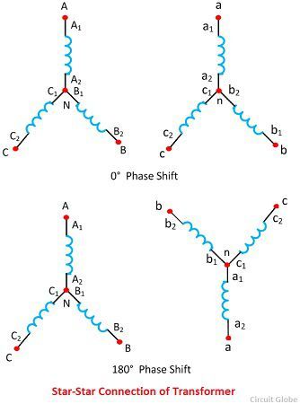
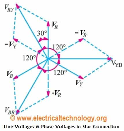
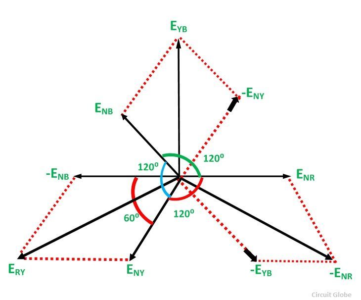
Phasor diagram of star connection. Therefore the three voltages e nr e ny and e nb are equal in magnitude but displaced from one another by 120 electrical. The terminals r y and b are connected together to form the star point also called the neutral n. Star star υ υ connection of transformer. This type of connection is commonly employed at the substation. Power in star connection. The voltages on primary and secondary sides can be represented on the phasor diagram as shown in the figure 2 below.
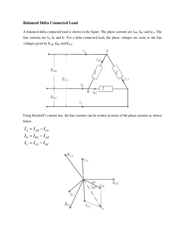
Figure 2 phasor diagram with voltages on primary and. 3 phase ac star circuit phasor diagram drawing steps to remember. The phase current is equal to the line current and they are in phase. Connection of three phases supply. Three phase current values in a 3 phase system. These results may also be obtained graphically from the phasor diagram shown in figure 3.
Star connection delta connection phasor sum solved problems duration. Let us consider the system of the figure 4 which is balanced y y three phase four wire system if the source voltages are given by 1. Or the sum of the all three phase powers is the total active or true power. In a three phase ac circuit the total true or active power is the sum of the three phase power. As the system is balanced a balanced system means that in all the three phases ie r y and b the equal amount of current flows through them. Values of line currents voltages and phase currents voltages.
Bthe lines r y and b are connected to the load. Phasor diagram showing phase and line voltages. The star connection is shown in the figure below. Then if the red phase is taken as the reference phase each individual phase voltage can. Phasor diagram of three phase supply. Formula of relation between phase and line voltage and current.
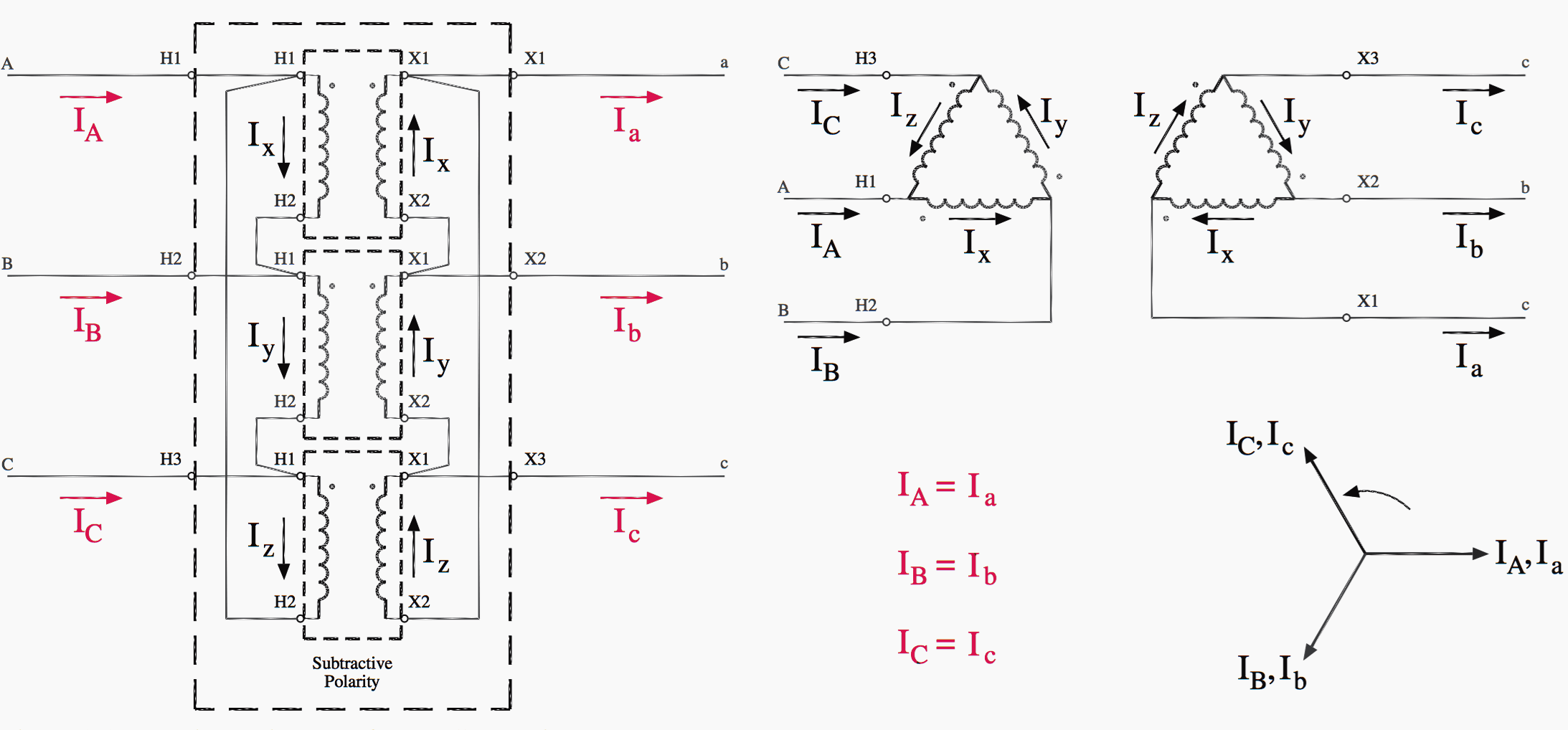
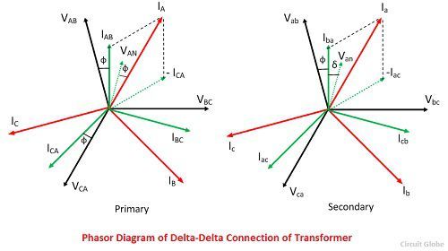
Phasor diagram for star connection in hindi duration. The phasors for a three phase balanced star or delta connected system are shown below. The three windings of the coils are connected together at points a 1 b 1 and c 1 to produce a common neutral connection for the three individual phases. The star star connection of three identical single phase transformer on each of the primary and secondary of the transformer is shown in the figure belowthe phasor diagram is similar as in delta delta connection. There is a mistake in the equations at 042. If the neutral is connected to the neutral of the load.
Rps tutorial 5232 views. Star delta transformer connection is commonly employed for power supply transformers. The phasor diagram of. In transformer primary is delta connection and secondary is star connection the primary v1110kv v222kv and power is 16 mva how to calculate current i1 and i2 if im using the formual p 3vphiphcos fi what is the value of cos fi.
