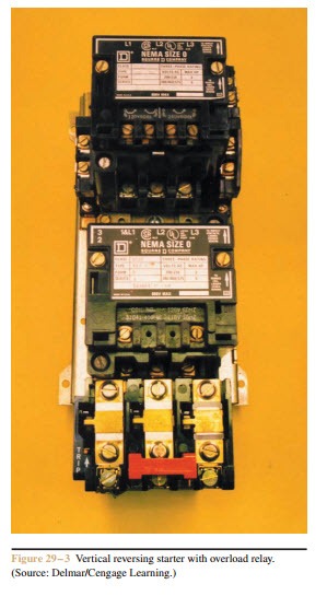
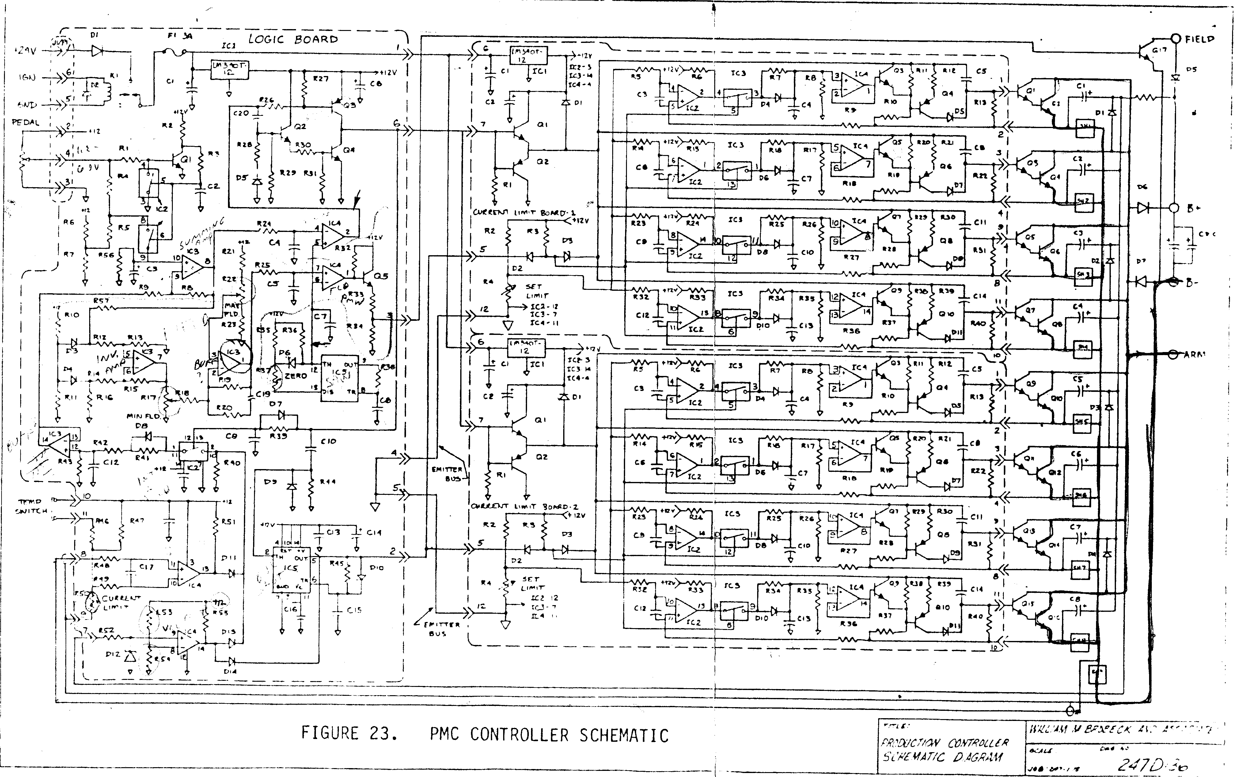
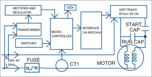
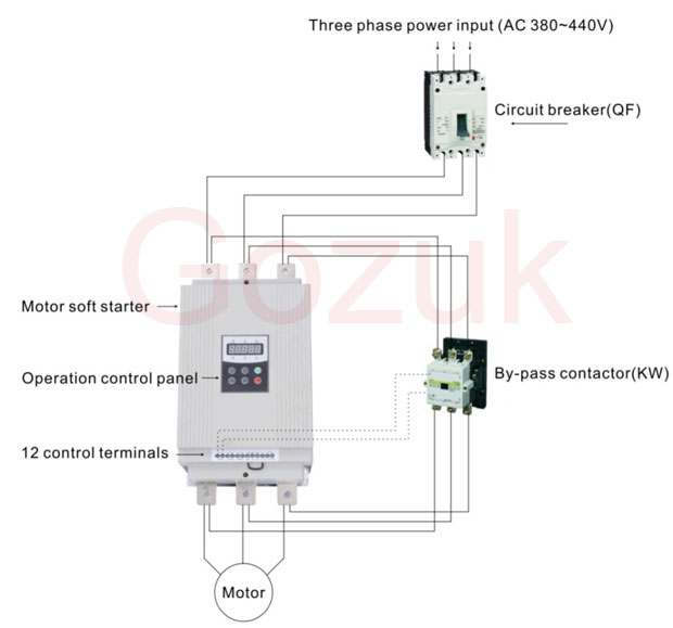
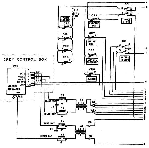
Basic wiring for motor control technical data. E bike controller wiring diagram collections of e bike controller wiring diagram list diagram electric bike.

Ed38f8 Rs232 Wiring Diagram Pdf Wiring Resources 2020
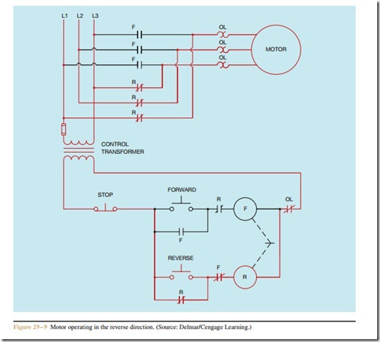
Motor control panel wiring diagram pdf. Power is supplied by connecting a step down transformer to the control electronics by connecting to phases l2 and l3. Show the control circuits only power circuits are omitted for clarity since they can be traced readily on the wiring diagrams heavy lines. A wiring diagram is a streamlined traditional photographic representation of an electrical circuit. Wiring diagrams show the connections to the controller. The lower voltage is then used to supply power to the left and right rails of the ladder below. Figure 1 a motor controller schematic.
2018 24v36v48v 250w350w bldc motor speed controller 6 mosfet dual. It shows the elements of the circuit as streamlined shapes and the power and signal links between the gadgets. Wiring diagrams sometimes called main or construction diagrams show the actual connection points for the wires to the components and terminals of the controller. The contacts m will be controlled by the coil mthe output of the motor starter goes to a three phase ac motor. E bike controller wiring diagram recent wiring diagram electric bike. Assortment of electrical control panel wiring diagram pdf.
A wiring diagram gives the necessary information for actually wiring up a group of control devices or for physically tracing wires when trouble shooting is necessary. Three phase motor connection schematic power and control wiring installation diagrams. Three phase motor connection stardelta without timer power control diagrams. Motor 3ct to 120 v separate control ot is a switch that opens when an overtemperature condition exists type mfo and mgo only t1 t3 motor 3 2 l2 t2. 36v 800w set electric bike controller twist throttle brake lever. Motor control wiring diagram pdf wiring diagram is a simplified usual pictorial representation of an electrical circuitit shows the components of the circuit as simplified shapes and the facility and signal associates with the devices.
Wiring diagram book a1 15 b1 b2 16 18 b3 a2 b1 b3 15 supply voltage 16 18 l m h 2 levels b2 l1 f u 1 460 v f u 2 l2 l3 gnd h1 h3 h2 h4 f u 3 x1a f u 4 f u 5 x2a r power on optional x1 x2115 v. Star delta y δ 3 phase motor starting method by automatic star delta starter with timer.
