Wiring a 2 way switch how to wire a 2 way switch how to change or replace a basic onoff 2 way switch wiring a 3 way switch how to wire a 3 way switch how to wire a 3 way switch circuit and teach you how the circuit works. The red and black are used for hot and the white neutral wire at the switch box allows for powering a timer remote control or other programmable switch.

Boat Building Standards Basic Electricity Wiring Your Boat
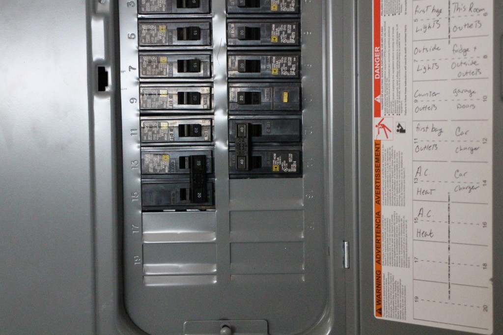
Home electrical wiring circuit diagram. For example a stick frame home consisting of standard wood framing will be wired differently than a sip or structured insulated panel home because of access restrictions. A split load cu. An electrical ground is a safety system that provides a safe path for electricity to follow in the event of a short circuit electrical surge or other safety or fire hazard. Automatic ups system wiring circuit diagram for home or office new design with one live wire. With the light at the beginning middle and end a 3 way dimmer multiple lights controlling a receptacle and troubleshooting tips. Having a map of your homes electrical circuits can help you identify the source of a problem.
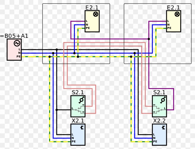
Because the electrical code as of the 2011 nec update requires a neutral wire in most new switch boxes a 3 wire cable runs between the light and switch. 2 such rings is typical for a 2 up 2 down larger houses have more. Wiring a 4 way switch. Wiring diagrams for 3 way switches diagrams for 3 way switch circuits including. The installation of the electrical wiring will depend on the type of structure and construction methods being used. Wiring diagrams wiring diagrams for 2 way switches 3 way switches 4 way switches outlets and more.
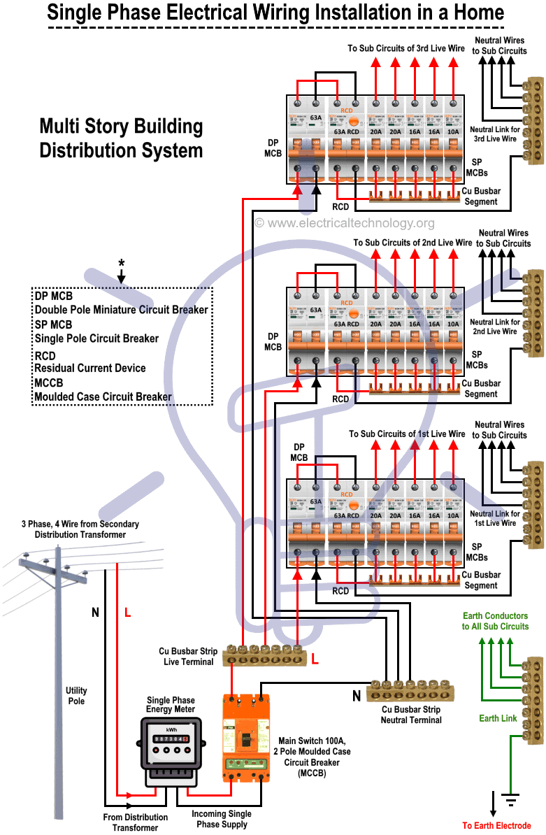
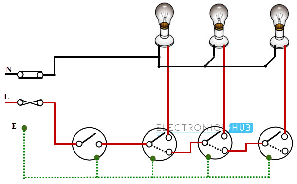
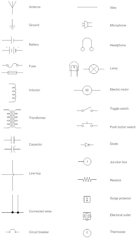
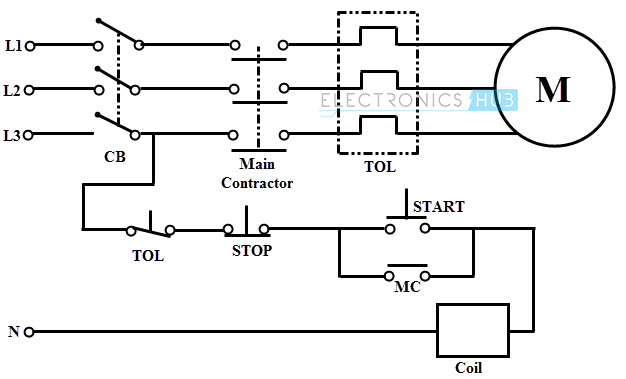
What is intermediate switch its construction working principle and using in different electrical wiring lighting etc circuits. A diagram that uses lines to represent the wires and symbols to represent components. Ring circuits from 32a mcbs in the cu supplying mains sockets. In modern home wiring systems each circuit has its own ground wire that leads back to the service panel. Typical house wiring diagram illustrates each type of circuit. Live neutral tails from the electricity meter to the cu.
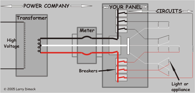
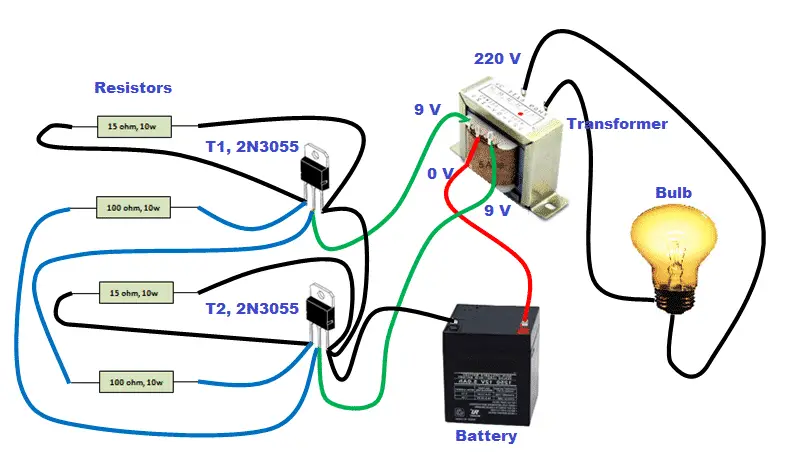
Automatic ups system wiring circuit diagram for home or office. Residential electric wiring diagrams are an important tool for installing and testing home electrical circuits and they will also help you understand how electrical devices are wired and how various electrical devices and controls operate. It moves along a hot wire toward a light or receptacle supplies energy to the device called a load and then returns along the neutral wire so called because under normal conditions its maintained at 0 volts or what is referred to as ground. A diagram that represents the elements of a system using abstract graphic drawings or realistic pictures. Electricity travels in a circle. This is an updated version of the first arrangement.
In a typical new town house wiring system we have. Electrician circuit drawings and wiring diagrams youth explore trades skills 3 pictorial diagram.

