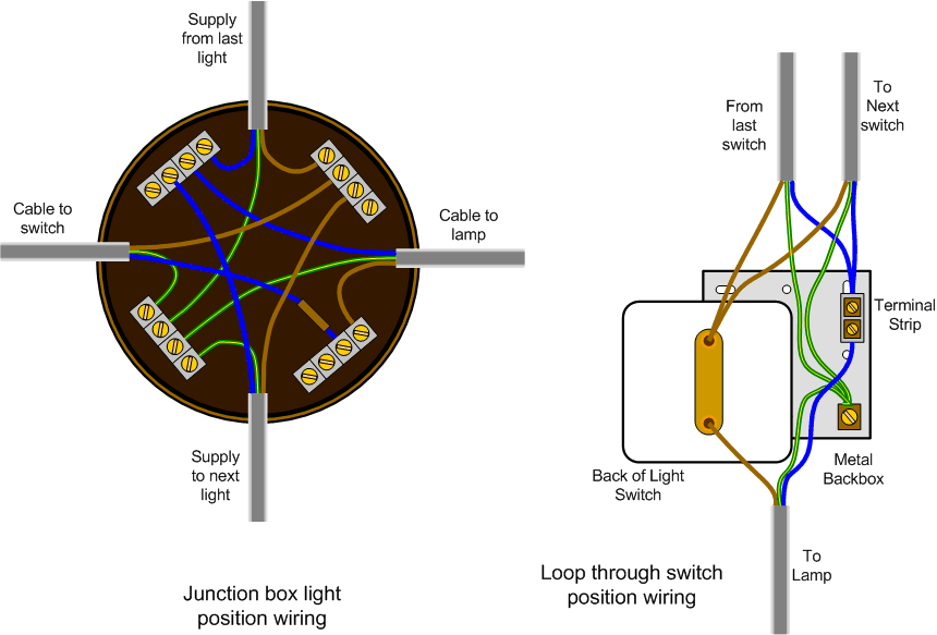
If you have a single light just eliminate the wiring that feeds the second fixture. We used an existing switch in an existing junction box.
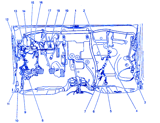
2000 Impala 3 8 Pcm Wiring Diagram Wiring Diagrams
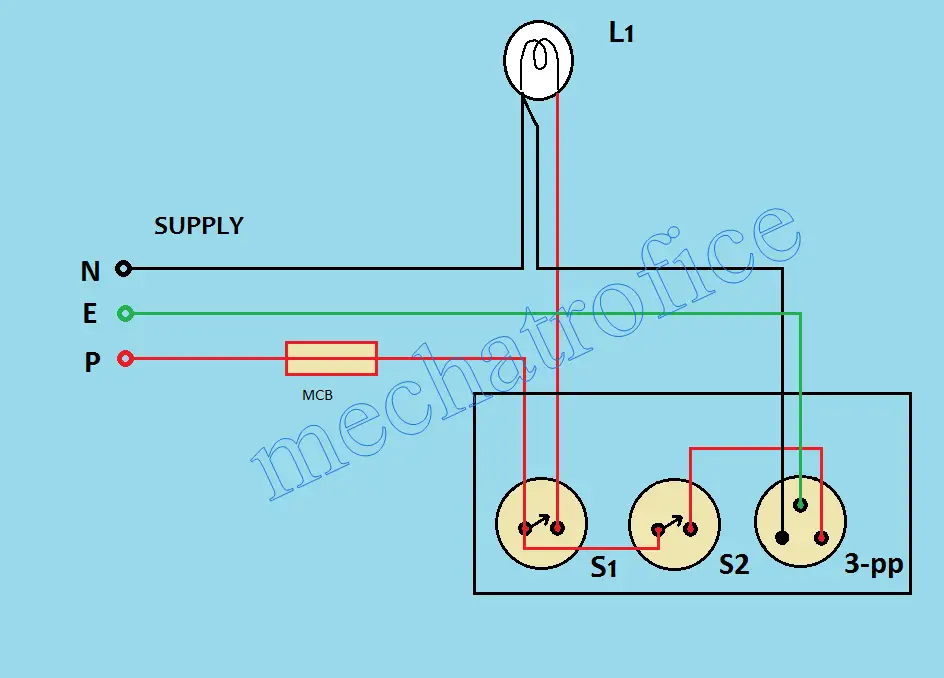
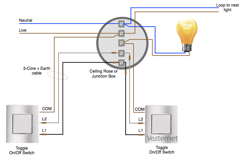
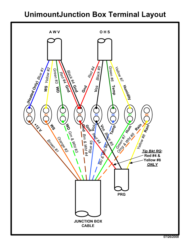
Lighting junction box wiring diagram. A wiring diagram is a simplified traditional pictorial representation of an electrical circuit. This would be cable a in the diagram below fig 2 which shows how the junction box is terminated. The terminals are where the connections will be made by inserting the wire core from either side or the wiring run and then screwing the terminal close to create a safe. Fig 2 the feed cable comes from a previous junction box or from the consumer unit the red black and earth wires are connected to separate terminals. The junction box should be wired as shown below. This repeats for each light in the circuit until we reach the last light.
Lighting circuits 20 amp. This repeats for each light in the circuit until we reach the last light. Line diagram of a one way lighting circuit using junction boxes fig 1. You may need to add a box and switch. 3 way junction box wiring diagram wiring diagram is a simplified tolerable pictorial representation of an electrical circuitit shows the components of the circuit as simplified shapes and the capacity and signal connections amid the devices. Junction boxes come with either 3 4 5 or 6 terminals so work our which you will need to complete your project.
Any standard outlet switch box or light fixture box can serve as an approved enclosure but where a wiring splice needs to occur in other locations along the circuit the approved enclosure is usually a junction boxa junction box is simply a standard electrical box that is. Explanation of above picture. This live feed now loops back out of the junction box cable b fig 2 and feeds power to the next ceiling light in the radial circuit junction box b fig 1. Wiring diagram of a one way lighting circuit using junction boxes fig 1. It shows the elements of the circuit as simplified forms and the power and signal connections between the devices. Lighting circuits using junction boxes.
This would be cable a in the diagram below fig 2 which shows how the junction box is terminated. Assortment of junction box wiring diagram. Both illustrations include additional light fixtures. The national electrical code nec dictates that no wiring splices are allowed outside of an approved enclosure. Junction box terminals and wiring. Fig 2 the feed cable comes from a previous junction box or from the consumer unit the red black and earth wires are connected to separate terminals.
The junction box should be wired as shown below. Your system must have a switch that can turn off the power to the sensor and light fixtures. This live feed now loops back out of the junction box cable b fig 2 and feeds power to the next ceiling light in the radial circuit junction box b fig 1. Explanation of above picture. An alternative method this uses the same wiring principles as the looped ceiling roses but here the connections are made in junction boxes rather than the ceiling rose. The junction box effectively replaces the ceiling rose.


