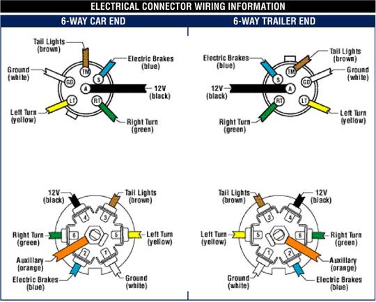
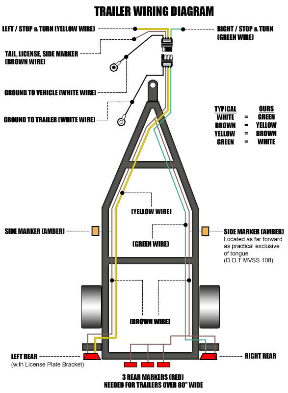
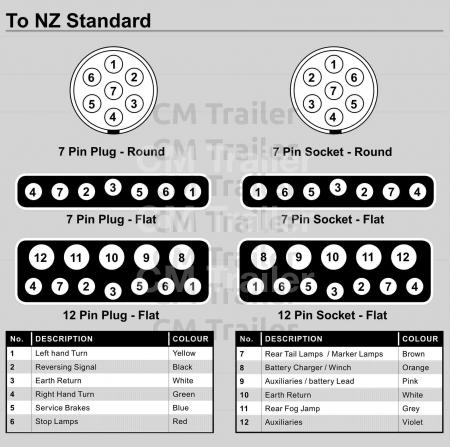
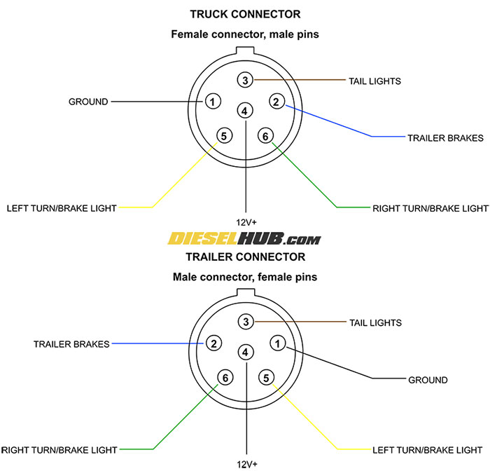
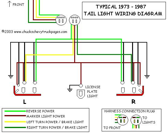
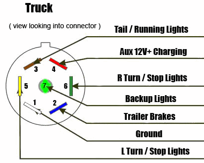
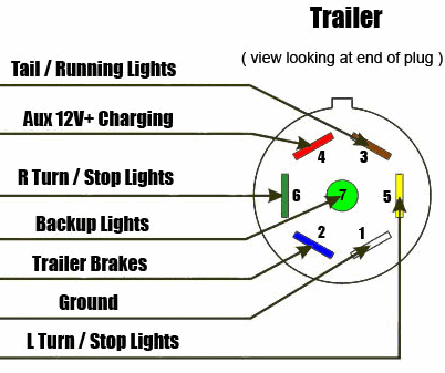
The trailer wiring diagram shows this wire going to all the lights and brakes. 6 way connectors 6 way connectors are available allowing the basic hookup of the three lighting functions running turn and brake the.
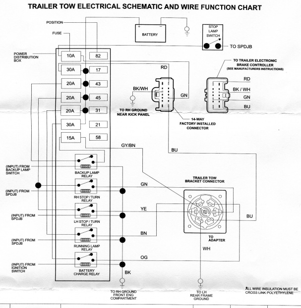
2011 F150 Electric Trailer Brake Help Ford F150 Forum
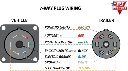
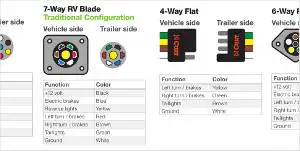
Trailer brakes wiring schematic. It reveals the parts of the circuit as streamlined forms as well as the power and signal connections in between the gadgets. Each of your new brakes will have two wires for the brake magnet. 7 way plug wiring diagram standard wiring post purpose wire color tm park light green battery feed black rt right turnbrake light brown lt left turnbrake light red s trailer electric brakes blue gd ground white a accessory yellow this is the most common standard wiring scheme for rv plugs and the one used by major auto manufacturers today. A wiring diagram is a streamlined standard pictorial depiction of an electrical circuit. The four wires control the turn signals brake lights and taillights or running lights. One wire is for 12 volt power to the brake magnets and the other wire should be grounded either to the trailer frame or to the main trailer ground wire.
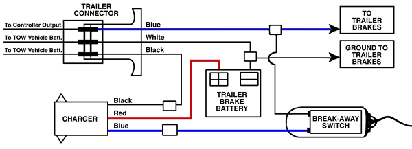
Connect the breakaway switchs other lead to the blue wire with a scotchlok connector. 4 way trailer connectors are. It shows the elements of the circuit as streamlined shapes and the power as well as signal connections in between the devices. Also it must connect with things if included that use the aux power and back up lights too. Locate the trailer connectors blue wire that supplies power to the electric brakes. You may have to cut into the trailer wirings sheathing to find the wire.
Assortment of electric trailer brake wiring schematic. If your trailer has 7 wires running all the way back to the brakes then yes you can tap into the existing wiring. To connect the electric system of your trailer to the vehicle you will be using special connector. Some trailer builders just connect this wire to the frame then connect the ground from all the other lights and accessories to the frame as well. A wiring diagram is a streamlined conventional pictorial representation of an electric circuit. They also provide a wire for a ground connection.
Various connectors are available from four to seven pins that allow for the transfer of power for the lighting as well as auxiliary functions such as an electric trailer brake controller backup lights or a 12v power supply for a winch or interior trailer lights. Variety of jayco trailer wiring diagram. Trailer wiring diagrams trailer wiring connectors. Below is the generic schematic of how the wiring goes. When the vehicle is reversing thus turning off the trailers brakes. Above we have describes the main types of trailer wiring diagrams.
4 way trailer connectors are typically used on small trailers such as boat snowmobile utility and other trailers that that do not use brakes. As the name implies they use four wires to carry out the vital lighting functions. 4 pin trailer wiring diagram. Trailer wiring diagrams trailer wiring connectors.

