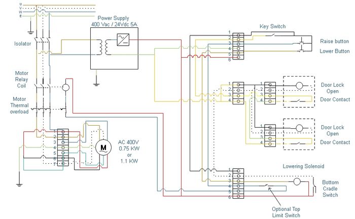
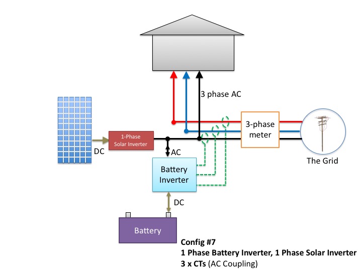
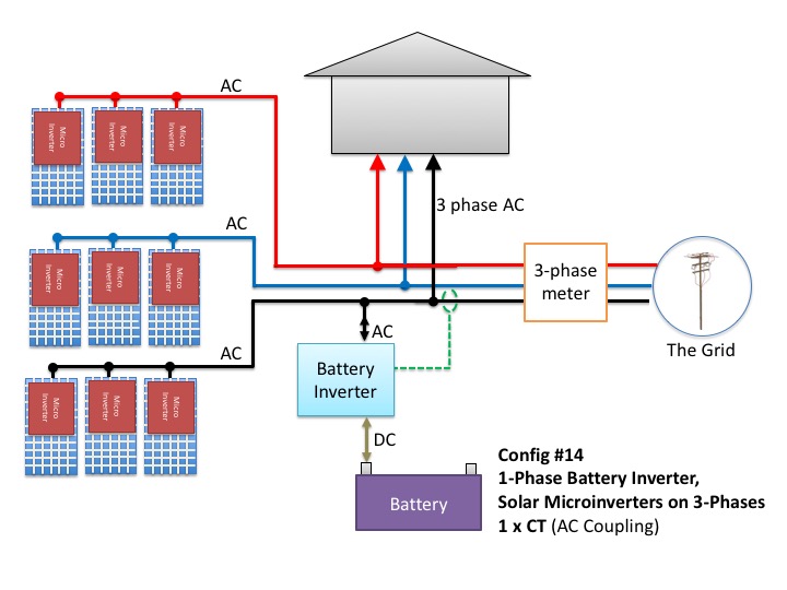
Cam operated rotary switches used to perform make and break the cam switches offers versatile mounting options in addition to standard. Switch off the mains supply before.
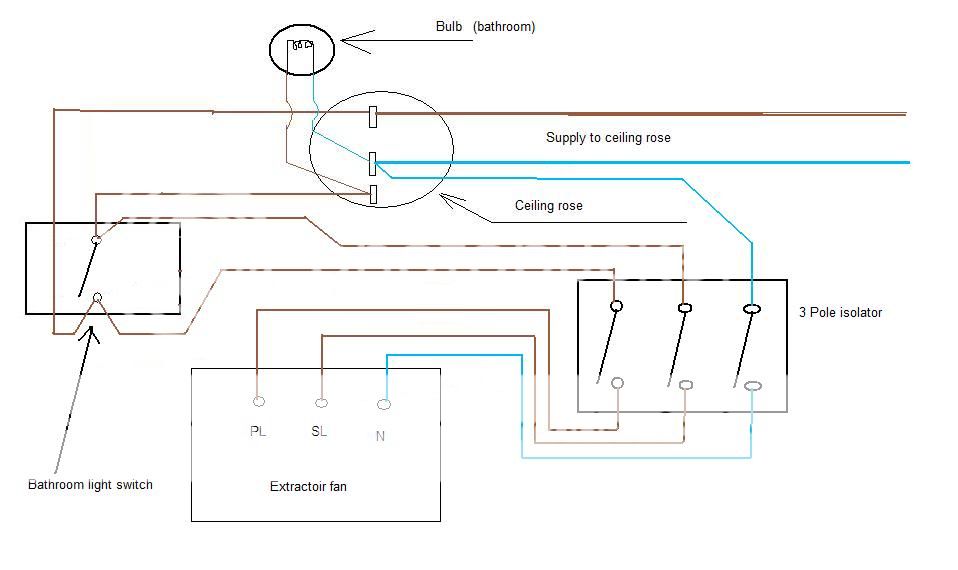
Single Pole Timer Switch Wiring Diagram Wiring Diagrams Dat
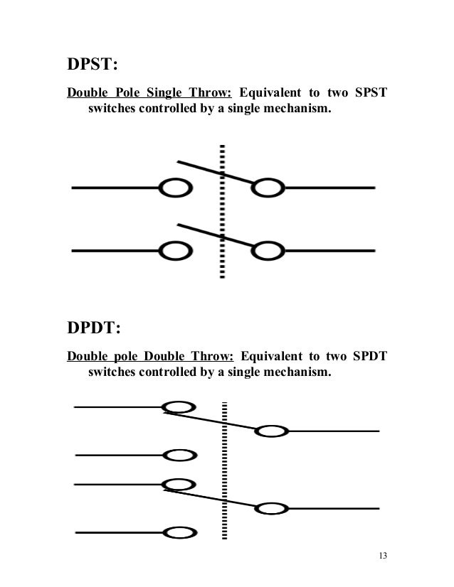
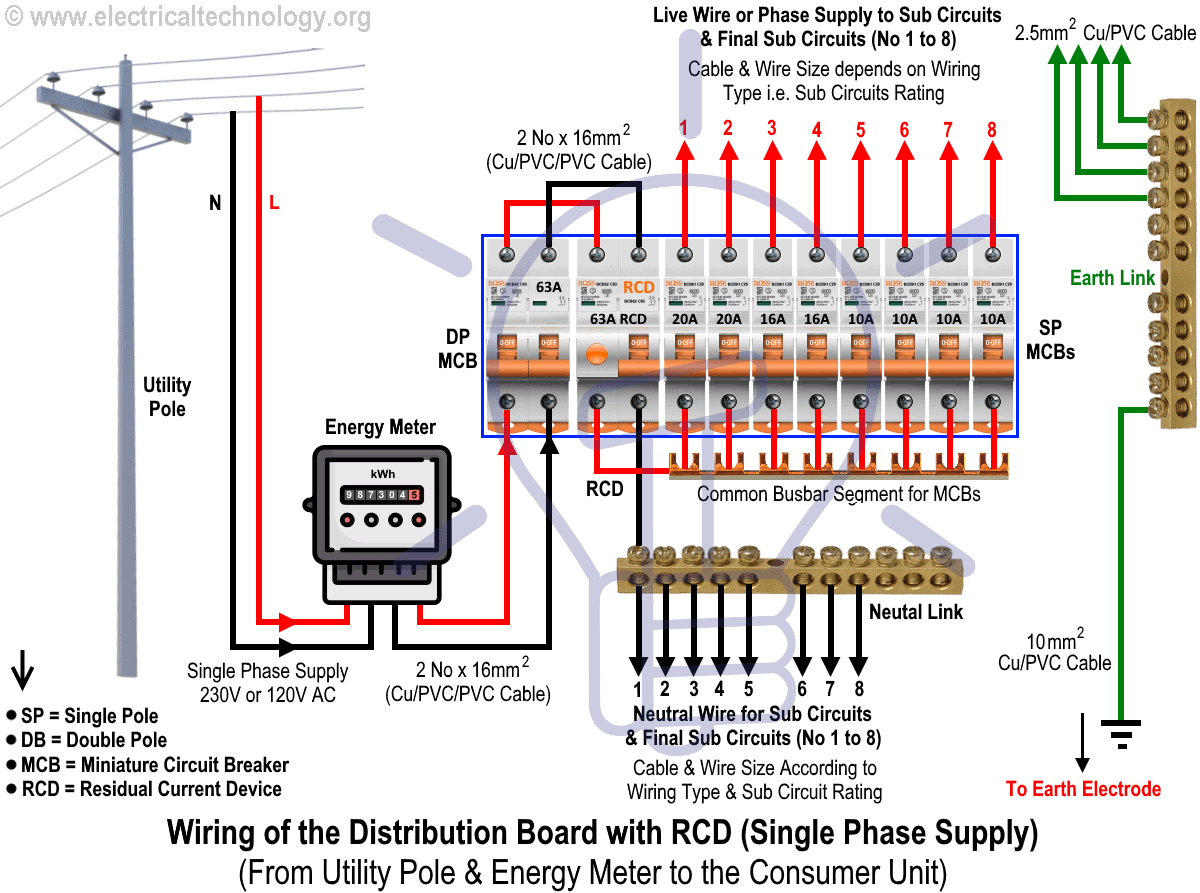
Wiring diagram for 3 pole isolator switch. I know its meant to isolate the line and neutral double pole but i am bit confused as to where my neutral should. The supplied switch from screwfix doesnt have a wiring diagram. It is absolutely vital that the terminal screws do not clamp on the insulation of the cables. The entire transfer switches provide 3 phase and 4 wire loads must be similar type either all 4 pole isolator. The 3 pole fan isolator can be installed in bathrooms but only under the strictest of conditions. It shows the components of the circuit as simplified shapes and the knack and signal associates in the middle of the devices.
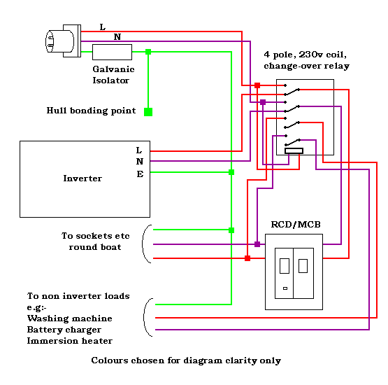
Whenever numerous generators as well as parallel switchgear are employed then the similar laws for deciding the use of 4 pole must be applied. A wiring diagram usually gives instruction practically the relative slant and bargain of devices and terminals upon the devices to encourage in building or servicing the device. This is significant for keeping the value of the ground fault system. In this video i show how to wire a 3 pole fan isolator switch for a timer fan using 3 core earth cable and for a non timer fan using twin earth cable. Ammeter switches with 0. It must be out of reach of any person using the bath or shower.
Voltmeter and ammeter selector switches. For guidance see the current edition of the iee wiring regulations bs 7671. I explain the wiring using basic wiring. Pole change switches and reversing pole change switches page 363. Connect the new socket or switch as shown in the appropriate wiring diagram in these fitting instructions taking care that only the copper conductors enter the terminals. To prevent electrocution do not work on any appliance live.
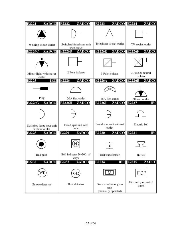
3 pole fan isolator switch wiring diagram wiring diagram is a simplified standard pictorial representation of an electrical circuit. Inside there are two earth connector fixings and then on the top of the internal box are l1 l2 and l3 connector positions with t1 t2 and t3 connectors positions on the bottom and finally theres an unlabled connection top and bottom which has no lettering but has a switch symbol on it. I guessing my live can go into supply side 1 or 2 or 3 as only single phase but the 4th pole has a switch symbol sticker on it inside the isolator does my neutral go into the remaining 12 or 3 or this forth switched pole.

