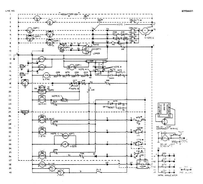
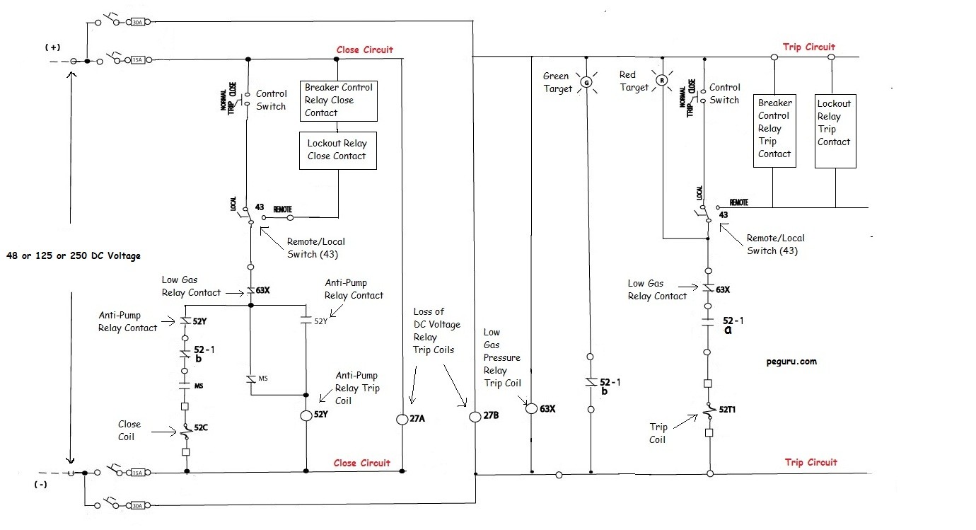
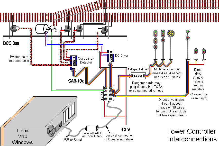
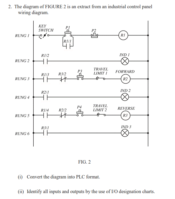
Lets go back and have a look at the control panel and try and figure out some of the connections by following a wiring diagram. Medium voltage load banks.
Reference Manual Infratech Official Site
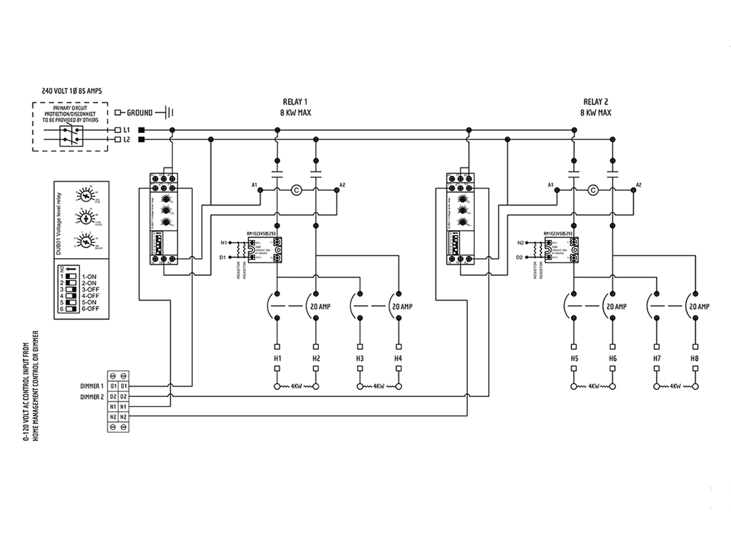
Control panel wiring diagram. It shows the elements of the circuit as streamlined shapes and the power and signal links between the gadgets. It is also common for a control cabinet to supply a higher voltage to other equipment such as motors. Trailer mounted load banks. It shows the parts of the circuit as simplified shapes as well as the power as well as signal links between the devices. One line diagram of simple contactor circuit. Assortment of electrical control panel wiring diagram pdf.
See all surge protective devices. It is a 2 door control panel on the front of which we have some switches that are connected to the plc inputs and outputs. Variety of cold room control panel wiring diagram. An example of a wiring diagram for a motor controller is shown in figure 1. You may also read. Motor wiringhow to wire a contactor and overload direct online starterhow to test a dol starterlearning dol starterdirect online starter dol starter working animation ryb electrical.
Basic wiring for motor control technical data. Multi speed 3 phase motor 3 speeds 1 direction power control diagrams. Resistive reactive load banks. Three phase electrical wiring installation in home iec nec. It shows the elements of the circuit as streamlined shapes as well as the power and signal connections between the devices. Dashed lines indicate a single purchased component.
A wiring diagram is a simplified traditional photographic depiction of an electric circuit. Note that symbols are discussed in detail later. Figure 1 typical wiring diagram. Radiator mounted load banks. How to connect a portable generator to home supply system three methods a simple circuit diagram of contactor with three phase motor. A wiring diagram is a streamlined traditional photographic representation of an electrical circuit.
Assortment of pump control panel wiring diagram schematic. As ive mentioned in the previous articles this is a control panel that is used for a system that turns wastewater into clean water. Figure 1 is a typical wiring diagram for a three phase magnetic motor starter. They can be used as a guide when wiring the controller. They show the relative location of the components. A wiring diagram is a streamlined traditional photographic representation of an electrical circuit.
See all load banks.


