The most common use of 3 wire control is a startstop control. I take one phase and neutral.
Three Phase Contactor Wiring Diagram Non Stop Engineering
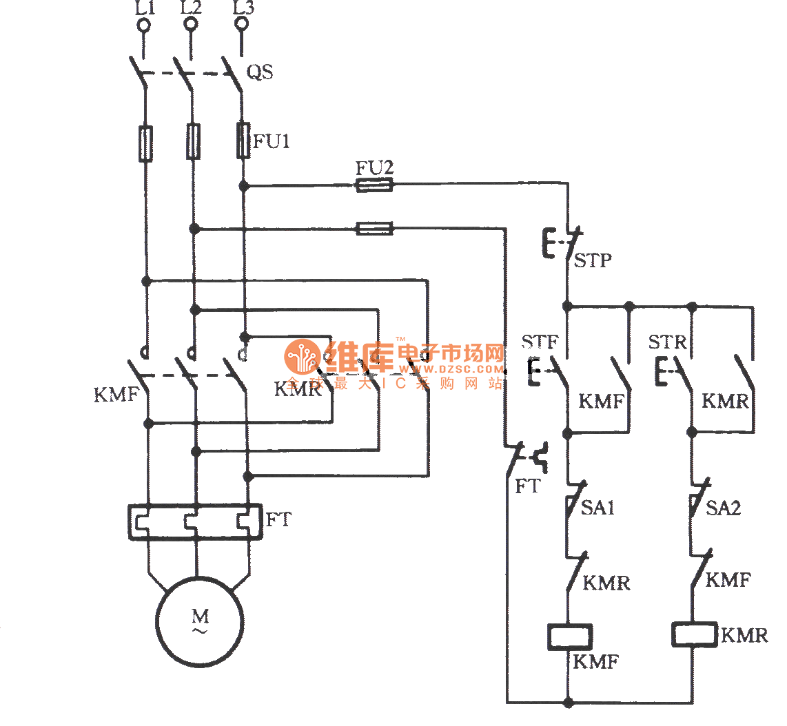
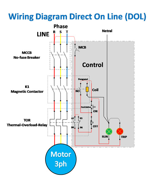
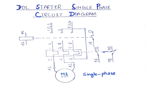
3 phase contactor wiring diagram start stop. How to wire a contactor and. How to do contactor wiring for 3 phase induction motor with 3 pole circuit breaker overload relay nonc push button switches in this tutorial post i will tell you about motor contactor wiring and its diagram. Start stop 3 wire control. The below wiring diagram shows how we would assemble a complete motor starter with a startstop button for a single phase motor utilizing a 3 pole contactor. Contactor wiring for 3 phase motor with circuit breaker overload relay diagram. For 3 phase induction motor startstop we use always mc contact or.
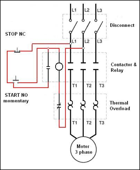
See image below for an example of 3 wire control being used to pull in a contactor to start a 3 phase motor. Using this method the current is balanced between the 3 poles on the overload. When you press the start button and the stop button is not pressed the 24vdc relay energizes and it pulls in the r1 contactor that feeds three phase power to the motor. A wiring diagram is a simplified conventional pictorial representation of an. Depressing the stop button breaks the circuit de energizing. I operation depressing the start button energizes coil m hold in contacts m and maintains the circuit after the start button is released.
What you dont know about 3 phase contactor wiring diagram start stop could be costing to more than you think. The following diagram depicts 3 phase non reversing motor control with 24 vdc control voltage and manual operation. 1 j start 2 3 stop i no. In above contactor wiring diagram i shown 3 phase 440 volts 4 wire system. A wiring diagram is a simplified traditional pictorial depiction of an electric circuit. Full voltage non reversing 3 phase motors.
Then you connect the 2 motor leads to t1 and t3. Its is a type of electric relay which can switch the 3 electric connections easily. Start stop control wiring diagrams single station basic circuit r 1 klai. Collection of 3 phase contactor wiring diagram start stop. Wiring most schematics utilize straight lines to symbolize the wires that connect components to one another. It reveals the elements of the circuit as simplified forms and also the power and signal links between the gadgets.
I zl ii i i ii i i fo 0. We will use a contactor an auxiliary contact block an overload relay a normally open start pushbutton a normally closed stop pushbutton and a power supply with a fuse.


