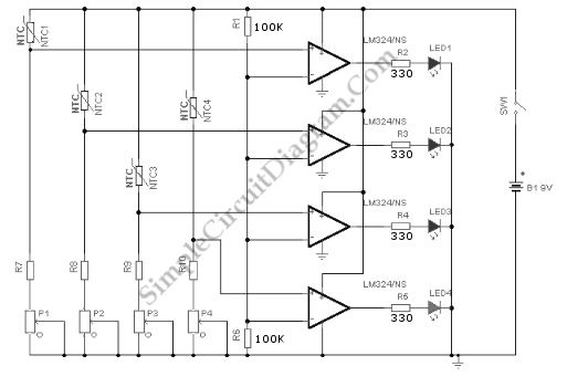
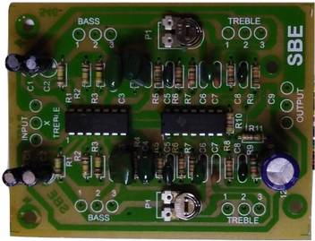
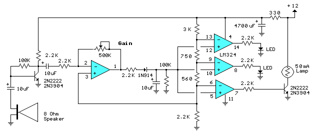
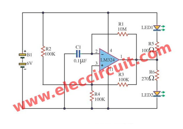
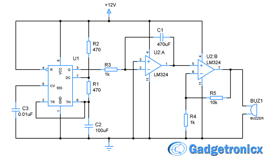
Use regulated power supply and nice filtering the dc current to get the sound output so less hum and more tone performance. This op amp ic has 4 operational amplifiers but in this circuit only 2 op amps are used.
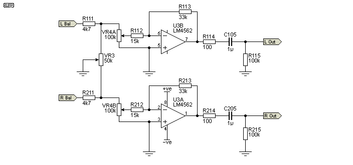
Hi Fi Preamplifier
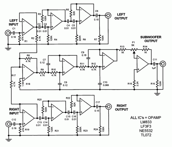
Lm324 tone control circuit diagram. This is a very basic circuit diagram of 3 band tone control. This is must before audio level controller. By using a single chip lm324 basic op amp to control and adjusting the tone. Therefore the output currents up to 85ma it also has significant short circuit protection too. Here is two tone control circuit diagram which can be used to make a tone control at home easily. Now i want to suggest you this circuit has 2 forms are.
We have two circuits both transistors op amp as main so smaller but high gain signal. Two 100k variable resistor is used in both circuit. With on the lm324 ic number includes 4 op amps. Bass booster circuit diagram this bass booster circuit is made using the quad op amp ic lm324. Input capacitor c1 blocks dc and sets the minimum low frequency response of the tone control circuit at approximately 16 hz 3 db with the value of 22 µf. This is bass treble tone control circuit diagram as ideas.
This circuit provides low pass filter of input audio which produces a low frequency of input and high frequency is blocked. This basic tone control circuit was originally intended for home audio use but should be able to be hacked into an effect circuit with very minor modification. The properties of frequency response time from 0 hz to 200 khz the r1 10ohm and c1 001uf are for control of isolates within and r is the 10 ohms to. Resistance value of resistor r1 is left up to the user depending on gain needs r2 is unknown for experiment purpose. You can make this and fix this for your homemade audio player speaker. The 1st circuit used an op amp ic 741 some pf capacitors and some resistors.
Which low quality than active tone control. This circuit needs voltage supply about 12v to 15v dc ct. And 3 op amp is applied to parallel together. You used to see the passive tone control circuit. Audio tone control schematic diagram the input buffer amplifier provides a gain of approximately 2 rfrin with the specified resistor values. Representative circuit diagram onefourth of circuit shown output bias circuitry common to four amplifiers vcc veegnd inputs q2 q3 q4 q5 q26 q7 q8 q6 q9 q11 q10 q1 24 k q25 q22 40 k q13 q14 q15 q16 q19 50 pf q18 q17 q20 q21 20 k q24 q23 q12 25.


