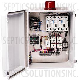
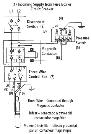
Single phase submersible pump control box wiring diagram 3 wire submersible pump wiring diagram in submersible pump control box we use a capacitor a resit able thermal overload and dpst switch double pole single throw. Today i open a submersible pump control box and change the change the motor capacitor because the old capacitor weakened and i replace it with new one.

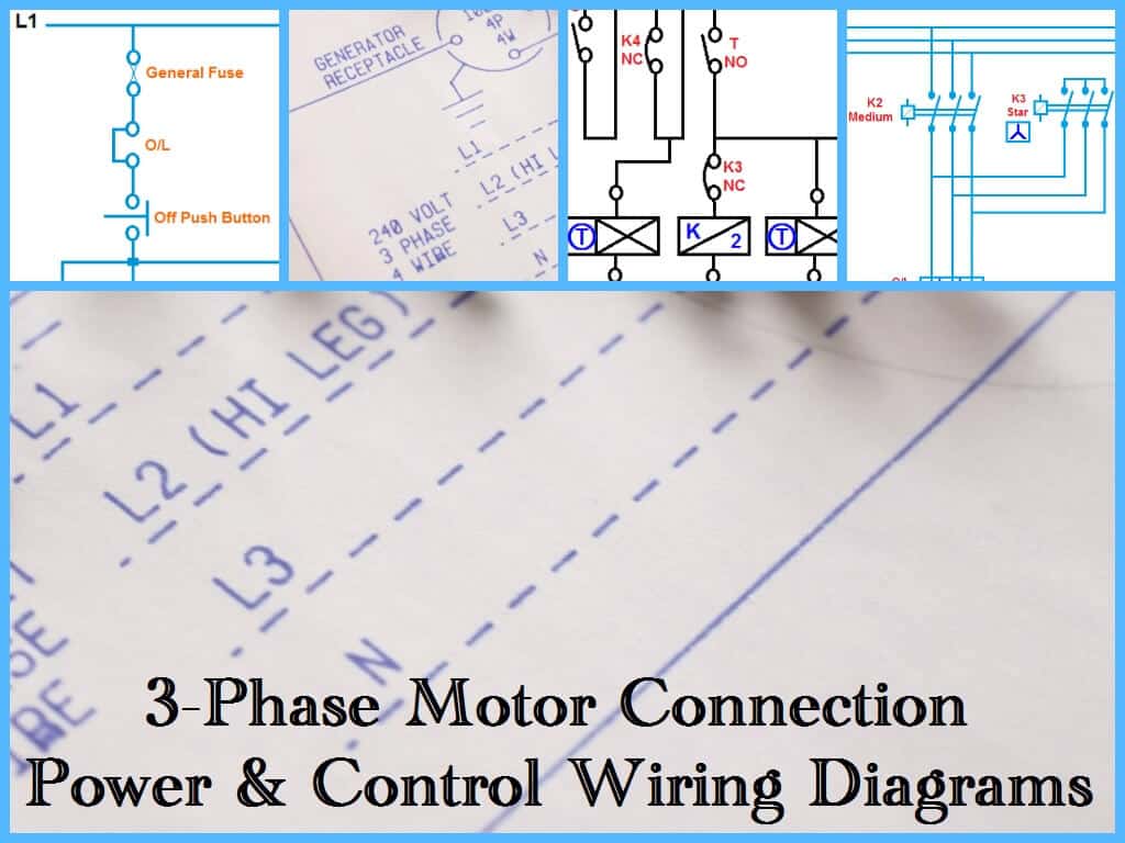
Three Phase Motor Power Amp Control Wiring Diagrams
Submersible pump control panel wiring diagram. In this video i have presentation about submersible pump control wiring diagram submersible pump box control wiring diagram no nc auxiliary contact working procedure. Jun 19 2017 single phase 3 wire submersible pump control box wiring diagram or single phase submersible pump starter wiring diagram and wiring installation guide. It shows the elements of the circuit as streamlined forms and the power and signal connections in between the devices. The wiring connection of submersible pump control box is very simple. The circuit is built using 7805 regulator ic1 microcontroller mcu ic at89c4051 ic2 two bt139bta41 triacs two triac driver ics moc 3041 ic3 and ic4 three transistors t1 through t3 10a 50hz current transformer ct1 and a few discrete components. How does no nc normally.
1 111213 page 27 control box wiring diagram cb1456c b1463 l1 460 vac three phase wiring external 3 phase connections 460 vac power source circuit breaker red white black l1 l2 l3 green ground g on indicator lamp m a2 a1 43 2 3 4 1 stop float switch start float. Collection of submersible pump control box wiring diagram. A submersible pump can be either two or three wire regardless of the voltage coming from the panel so start at your pump and follow the conduit back. Today i will share with the complete diagram of. 3 phase submersible pump wiring diagram. St4st6 series submersible pumps operation and parts manual rev.
2 shows the circuit diagram of the submersible motor control panel. A wiring diagram is a simplified traditional photographic depiction of an electrical circuit. Collection of 3 wire submersible pump wiring diagram. Single phase submersible pump starter wiring diagram. Here is the complete guide step by step. A wiring diagram is a streamlined traditional photographic representation of an electrical circuit.
If it runs straight to the pressure switch it is a two wire. It shows the elements of the circuit as simplified forms and also the power as well as signal links between the devices. If the conduit runs into a control box before continuing to the water pressure switch chances are you have a three wire pump. Not only a contactor but also i install the thermal overload relay which will protect the motor form burning in case of over current flow to the circuit. In which i control a three phase submersible pump motor using magnetic contactor. I saw the diagram on the back side of box which locked on my mobile by using mobile camera.


