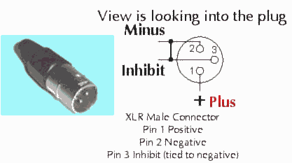
Xlr pin 2 inhibits vehicle operation when pulled to battery negative. A wiring diagram is a simplified standard photographic depiction of an electric circuit.

Dhd Documentation
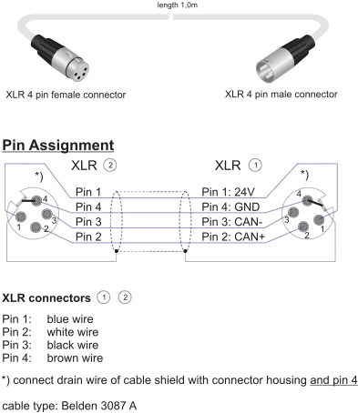
Xlr connector wiring diagram. Pin 2 just lets the unit sense when the charger is connected and disables the drive so you dont run away with the charger cord attached. The rear view is the end you solder from here are the connections on each pin. When connecting a 3 pin xlr to one rca you use the same wiring as if you were connecting an xlr to a 14 jack plug. Visit the post for more. The following is the aes industry standard for balanced audio xlr wiring commonly known as pin 2 hot. Xlr connector wiring diagram together with 3 pin mini 5 pin xlr wiring diagram for center u2022 4 dmx diagrams rh gregorywein co 3 female end cable wiring xlr cable wiring diagram.
Xlr to 1x rca. 3 pin xlr wiring diagram cable wiring etc cable designed for being cut into standard mic cables may have 2 pairs of wire and a shield around the outside in that case pair the colors together and make sure they go to the same pin number on each end. Xlr pin 1 battery positive. Collection of xlr wiring diagram pdf. 3 pin xlr wiring standard. A wiring diagram is a basic aesthetic depiction of the physical connections and also physical format of an electrical system or circuit.
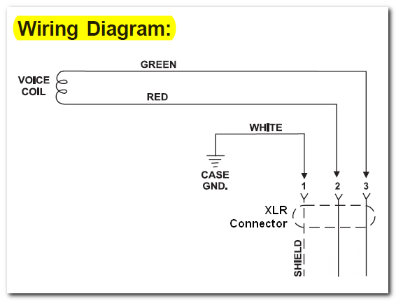
Xlr pinout balanced a balanced system is used in pro audio systems xlr wiring diagram shown below with an overall screen covering a twisted pair. It demonstrates how the electric cords are adjoined and could likewise show where fixtures and elements might. 3 pin xlr audio pinout. Xlr to 1 4 wiring diagram this is images about xlr to 1 4 wiring diagram posted by janell a. The above diagram shows you the pin numbering for both male and female xlr connectors from the front and the rear view. Wiring diagram for xlr connector refrence xlr to mono jack wiring exactly what is a wiring diagram.
Xlr pin 3 battery negative. The positive and shield of the xlr are joined together either at the xlr end or the rca end. Pin 2 on the xlr is hot and carries the positive going signal whilst pin 3 is cold and provides the return. Some manufacturers especially in vintage equipment do not follow this standard and instead reverse the polarity of pin 2 and 3. The rear view is the end you solder from here are the connections on each pin. It shows the elements of the circuit as simplified forms and the power and also signal connections between the tools.
Bueno in xlr category on nov 20 you can also find other images like wiring diagram parts diagram replacement parts electrical diagram repair manuals engine diagram engine scheme wiring harness fuse box vacuum diagram timing belt. 3 pin xlr connectors are standard amongst line level and mic level audio applications.


