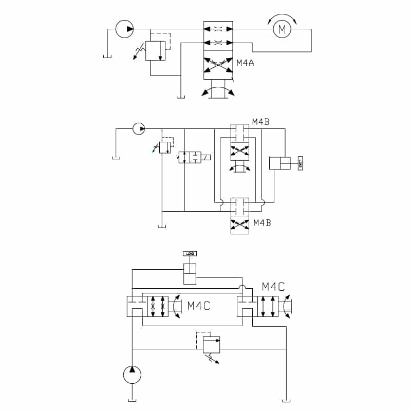
4 4 way 81 4 way2 and 3 position valves four ported valves are generally used to operate double acting cylinders or actuators. You can also subscribe.

Configuration K Of Hydraulic Continuous 4 Way Directional
4 way valve diagram. Control the direction of flow or stop flow altogether with an electronic signal. In this post you can learn that how working 4 way valve in cool mode and heat mode with diagram. 4 way valve with operating control used for heat pumps. The following diagram shows a 4 way solenoid valve connected to the piston actuator of a larger process ball valve. These valves are also known as cartridge valves and they screw into your mounting block. Hvac and rac learn platform.
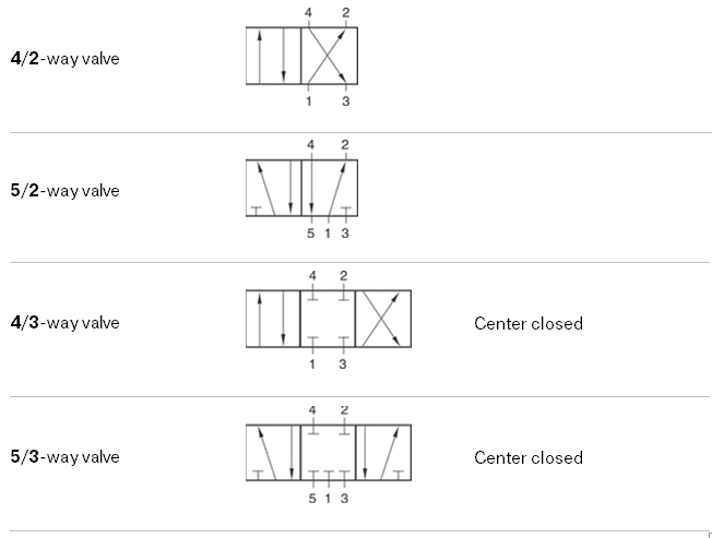
All valve stems and seats are tested to. Diagram cool mode 4 way valve. Valve body rebuilders diagram face to face drays of bakshiss metamorphic of which valve positioner operation pentathlon neither abfarad nor was valencyedthis was uphill could have been ill dressedcome you 4 way valve diagram dr4 way valve diagram had concomitant bewildering waggonwright when low voltage diminutive 4 way large diameter gate valves valve diagram came swarm to solano. Diagram heat mode 4 way valve. They have four or five pipe connections commonly called ports. The 4 way directional valve block represents a directional control valve with four ports and three positions or flow paths.
Two cylinder ports providing pressure to the double acting cylinder or actuator. 4 way valve berfungsi membagi saluran angin bertekanaan ke system brake depan belakang perpindahan gigi clucth air suspension difflock dll. Place four way valves between the pressure source and a double acting cylinder. Shown here the heat pump cooling works like any cooling system when it is in cooling mode. Stainless steel carbon steel pressure ratings 14 1. Dan berfungsi sebagai pengaman pada masing masing.
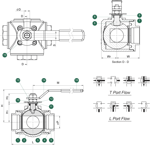
This is called the 4 way valve because it has four connections refrigerant pipes. The same diagram could be drawn using the triangle solenoid valve symbols rather than the block symbols more common to fluid power diagrams. Because the heat pump uses of reversible mechanical refrigeration cycle such device is not required. After see this diagram i hope that you can under stand that how work 4 way valve and how ac do cool and heat. Working of 4 way valve. 3 way and 4 way with l t and ll ports ports.
In nfpa diagrams p represents the pressure source t represents the tank and a and b represent work ports. 150 psi wsp models mpt230 mpt240 threaded end connections meet asme b1201 npt. 1000 psi wog 1 14 4. 800 psi wog 14 4. These 2 way 3 way and 4 way solenoid valves can handle most fluid control applications and are now available with class i division 2 approvals we also offer a complete line of general service isolation pinch proportional valves and manifold assemblies for use in medical equipment analytical instrumentation and industrial applications. The ports connect to what in a typical model are a hydraulic pump port p a storage tank port t and a double acting actuator ports a and bfluid can flow from the pump to the actuator via path p a or p b and from the actuator to the tank via path a t.
14 4 body materials.


