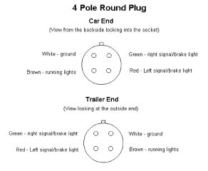
4 way trailer connectors are typically used on small trailers such as boat snowmobile utility and other trailers that that do not use brakes. Trailers longer than 15 feet and heavier than 1500 lbs must have a brake system that means another circuit for hydraulic brakes.
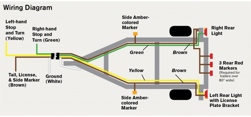
Wiring Diagram
Wiring diagram for trailer lights and brakes. The wires are colored differently using white for ground green for right turns and brakes yellow for left turns and brakes and brown for the tail lights. Trailer wiring diagrams trailer wiring connectors various connectors are available from four to seven pins that allow for the transfer of power for the lighting as well as auxiliary functions such as an electric trailer brake controller backup lights or a 12v power supply for a winch or interior trailer lights. The extra wire as a rule is used to power backup lights. Green right turn lightsbrakes. White ground wire. They also provide a wire for a ground connection.
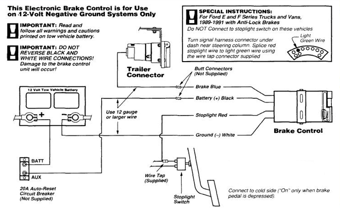
Electric trailer brake wiring schematic collections of electric trailer jack wiring diagram download. Some trailer builders just connect this wire to the frame then connect the ground from all the other lights and accessories to the frame as well. The trailer wiring diagram shows this wire going to all the lights and brakes. Round 1 14 diameter metal connector allows 1 or 2 additional wiring and lighting functions such as back up lights auxiliary 12v power or electric brakes. This should send 12v power to the pin on the 7 way that activates the trailer brakes. 2008 dodge ram 1500 trailer brake wiring diagram fresh dodge wiring.
The four wires control the turn signals brake lights and taillights or running lights. The black sometimes red 12v and blue electric brakes wire may need to be reversed to suit the trailer. Installing your 4 pin trailer wiring system is easy if you follow the correct procedure. The first thing you need to do is make sure that your connector works properly. Yellow left turn lightsbrakes. If your trailer has 7 wires running all the way back to the brakes then yes you can tap into the existing wiring.
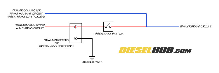
4 way trailer connectors are. When it is plugged it disengages hydraulic trailer actuator when you reverse so the trailer brakes are off at that moment. As the name implies they use four wires to carry out the vital lighting functions. Check with a test light or vom. Trailer wiring color code explanation. If the 7 way connector on your 7 way doesnt get 12v power when the manual override is used then you will want to sever the brake controller wire that goes to the 7.
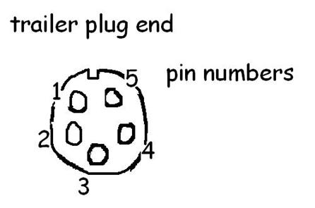
Also it must connect with things if included that use the aux power and back up lights too. Trailer wiring diagram 6 pin round 6 way trailer connectors are used in the following vehicle applications. One wire is for 12 volt power to the brake magnets and the other wire should be grounded either to the trailer frame or to the main trailer ground wire. On the tow vehicle end this should be the pin in the 5 oclock position see attached photo. Wiring diagram for stock trailer refrence lovely trailer wiring. Brown tail lightsrunning lights.
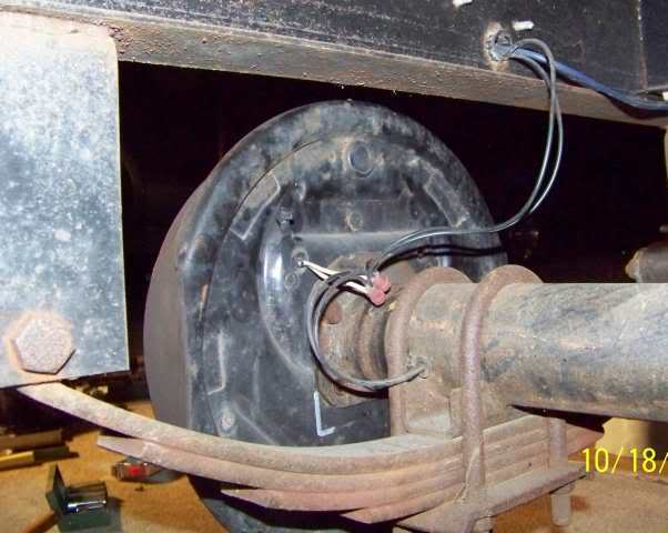
Each of your new brakes will have two wires for the brake magnet. Curt trailer brake controller wiring diagram control in wiring.


