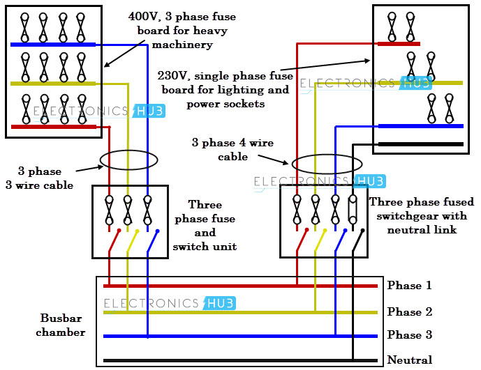
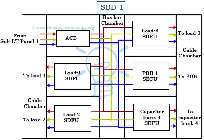
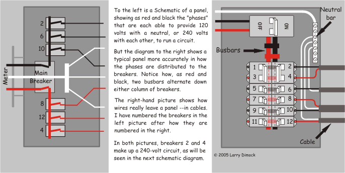
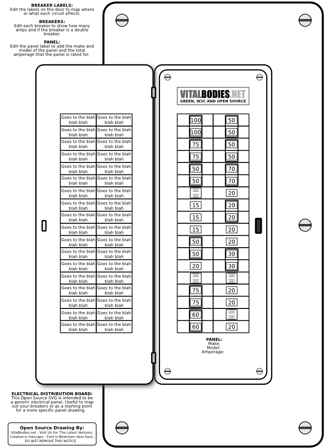
Grounds and neutrals in electrical panel. A 3 phase panel board wiring diagram or 3 phase distribution board wiring diagram.
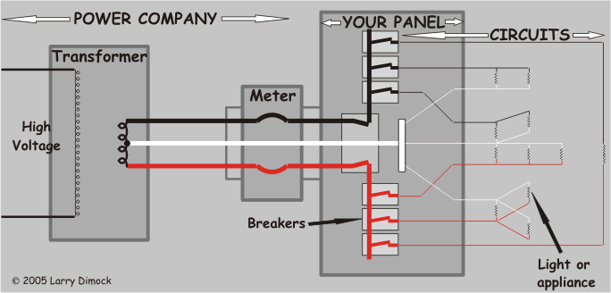
Your Home Electrical System Explained
Electrical panel board wiring diagram. The contacts m will be controlled by the coil mthe output of the motor starter goes to a three phase ac motor. Each page of the wiring diagram shows the exact wiring for. Electrical panel emt run armoured cable run bx 4x4 junction box 10 12 21 mm 21 mm figure 2circuit drawing line diagram. More about wiring a sub panel. Distribution board is a safe system designed for house or building that included protective devices isolator switches circuit breaker and fuses to connect safely the cables and wires to the sub circuits and final sub circuits including their associated live phase neutral and earth conductors. In which mccb circuit breakers volt meters ampere meter with current transformer light indicator earthing connection and bus bar with complete wiring diagram.
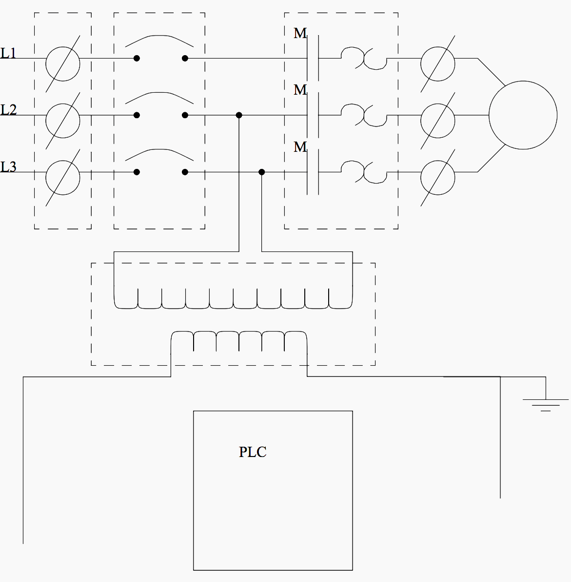
The one line diagram is similar to a block diagram except that electrical. If this helped you out. Figure 1 a motor controller schematic. Electrical panel board wiring diagram pdf best panel board wiring wiring diagram overcurrent relay refrence further electrical. In this video i explain exactly how i wired this panel and do my best to share all of the important information that you would need to wire a new main panel or load center. How to wire grounds and neutrals in sub panels all the neutrals and ground wire and terminal bars must be separated from each other and your sub feed should be a 4 wire cable that has a separated insulated neutral wire and a separate ground wire.
All the wiring that you see in the panel is done based on the wiring diagram. Distribution board is also known as fuse board panel board. Click on the image to enlarge and then save it to your computer by right clicking on the image. This is what we draw using autocad electrical. In a new home construction or a rewiring project the last step will be connecting all the wires to the circuit breaker box which is what this article describes. The lower voltage is then used to supply power to the left and right rails of the ladder below.
The electrical symbols will not only show where something is to be installed but what type of device is being installed. When looking at any switch diagram start by familiarizing yourself with the symbols that are being used. Power is supplied by connecting a step down transformer to the control electronics by connecting to phases l2 and l3. Assortment of electrical panel board wiring diagram pdf. This overview assumes that the electrical panel is installed on the wall of a utility area near where the main feeder wires come into the home and that all branch circuit wiring cables and conduit runs are already installed. What is distribution board.
A one line diagram or single line diagram is a simplified notation for representing an electrical system.
