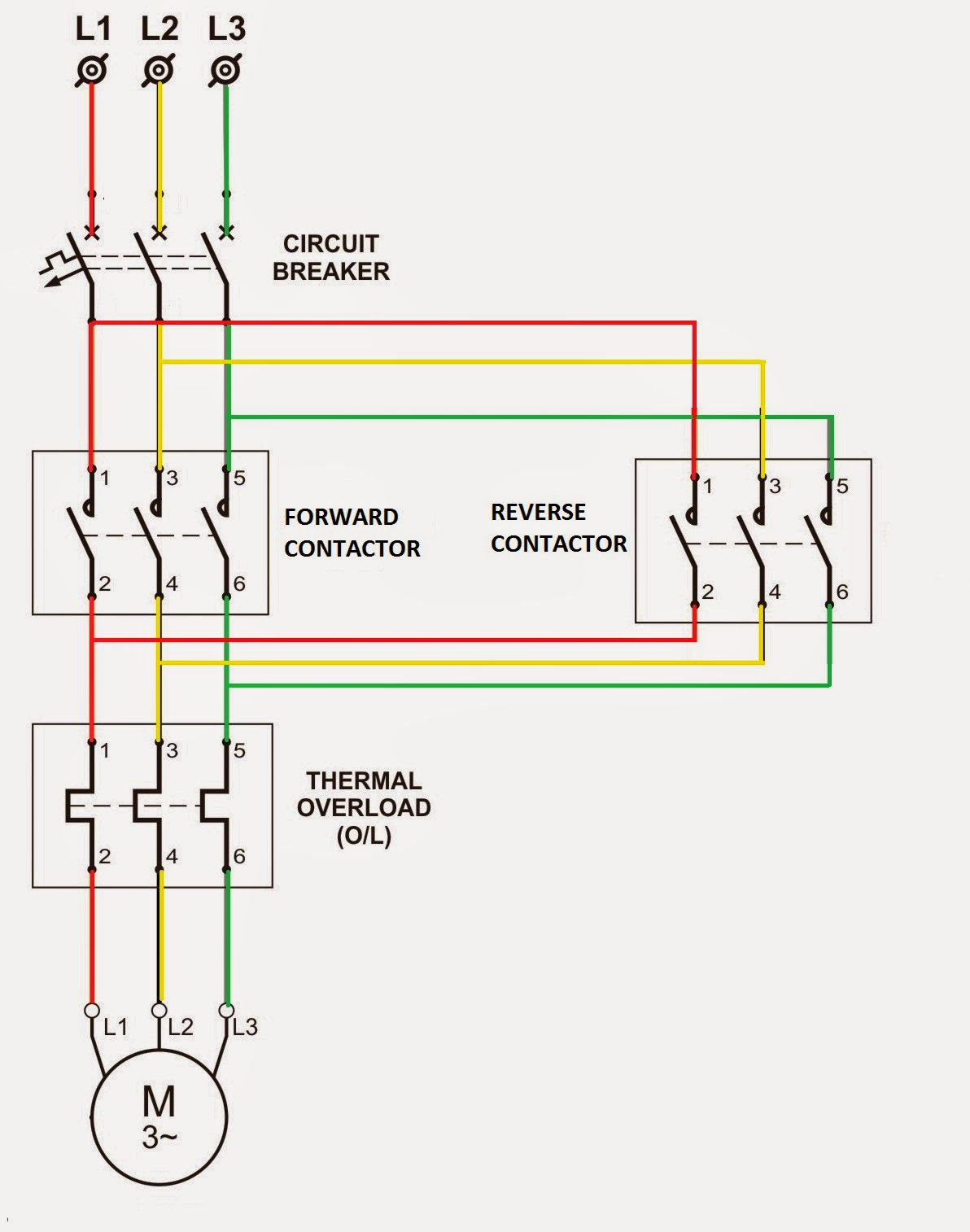
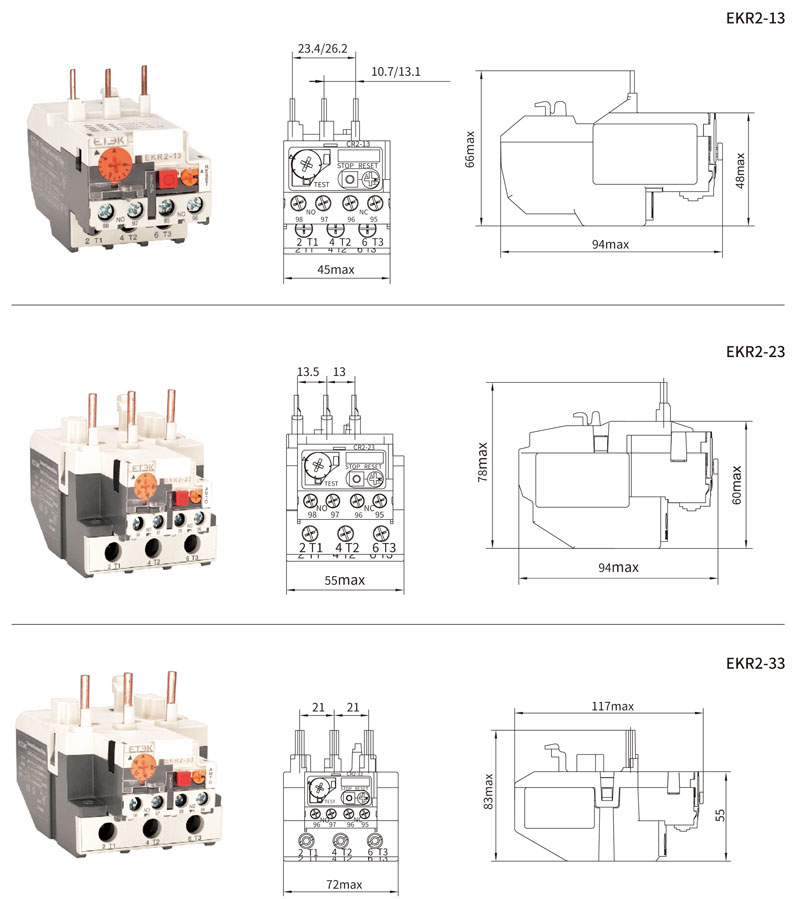
Overload relay connection diagram. Read more thermal overload.

How Does The Overload Relays Protect The Motor Electrical
Thermal overload relay connection diagram. Fill up the following data of relay under test. A thermal overload relay works in the. Basically thermal overload relay is an overcurrent protection of the simplest type. The device has trip class 10a. A contactor is a large relay usually used to switch current to an electric motor or another high power load. A relay type b relay range c max.
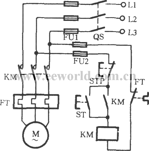
As an example if we have to select the range of overload relay for a motor with a full load current of say 10 amperes it should be from 7 to 12 amperes or as near to it as possible. It offers reliable and fast protection for motors in the event of overload or phase failure. Back up fuse rating 2. Ta25du 40 thermal overload relay. The wiring diagram of an overload relay is shown below and the connections of an overload relay symbol may seem like two opposite question marks otherwise like s symbol. Every motor must be protected from all possible faults to ensure prolonged and safe operation as well as time loss caused due to breakdown.
Although there are several types of overload relays available in the market however the most frequent type of relay is the. Almost all the industries rely on the electric motor to control its processes and production. Overload test 1m 1m dut 1m 1m from current source nc contact of relay connections of thermal overload relay for ol testing testing of thermal overload relay 1. In a wiring diagram the symbol for overload contacts may look like two opposed question marks or an s. Thermal overload is widely used for motor protection. An adjustment dial located on the unit allows the ampere trip settinga manual test button.
The ta25du 40 thermal overload relay is an economic electromechanical protection device for the main circuit. Easy and simple wiring diagram to make you learn easily watch the video and subscribe my youtube channel air. Though there are different types of overload relays the most common type is the bimetallic thermal overload relay. Contactor wiring and i hope after this post you will be able to wire a 3 phase motor i also published a post about 3 phase motor wiring with magnetic contactor and thermal overload relay but today post and contactor wiring diagram is too simple and easy to learn. 2 days ago i wired 380 to 440 volts contactor for a 3 phase motor and save these images of contactor in pc. Its is important to.
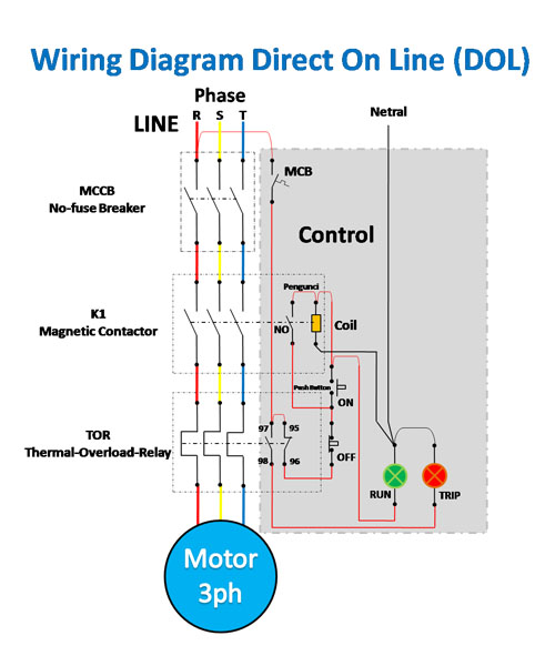
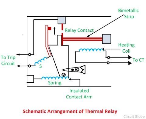
The overload relay connection diagram underneath shows the power and control connection diagram of the overload relay in a dol configuration. The overload relay workingfunction is discussed below. The working principle of thermal overload relay is quite simple but interesting. Large electric motors can be protected from overcurrent damage through the use of. Dol starter control and power wiring by using a fuse contactor overload relay motor. Figure below shows a typical thermal overload relay.
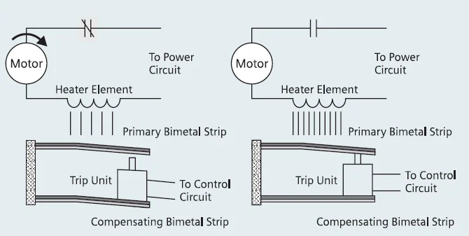
Overload relay principle of operation types connection. This type of overload relay uses two different types of metal strips that are bonded together and expand at different rates.
