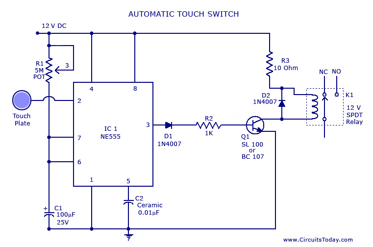
Controlling applications with google assistant home automation project in this project i will make a voice control home automation dev. Hello my loved people today i would to show you about how to make automatic switch on the light by voice or sounds automatic switch circuit.
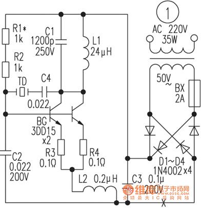
Voice Control Switch Circuit Switch Control
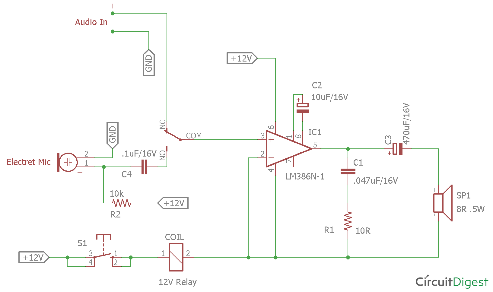
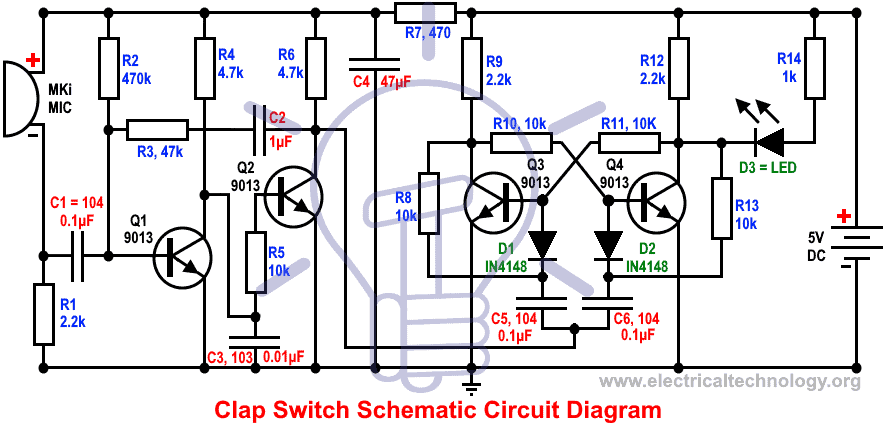
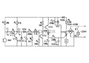
Voice control switch circuit diagram. This circuit uses an mc2830 to form a voice activated switch vox. A traditional vox circuit is unable to distinguish between voice and noise in the incoming signal. A single channel relay board is sufficient. In a noisy environment the switch is often triggered by noise or the activation sensitivity must be turned down. Code and explanation. The microphone preamplifieru1 receive input signal which will be amplified.
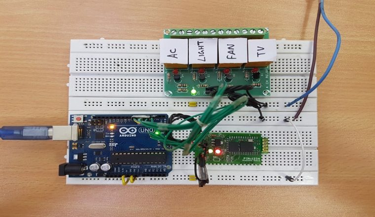
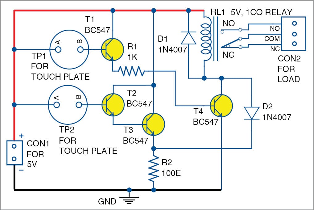
Voice commands are used to control different appliances. This circuit overcomes this weakness. In this project a simple voice activated home automation system is designed. The actuating threshold is set thru the volume potentiometer of the amplifier which command the vox circuit. Alternatively the relay circuit can be built as per the circuit diagram. The complete arduino code for voice controlled leds is given at the end.
After making the necessary connections we have to switch on the power supply to the circuit. This circuit consist of a schmitt trigger a relay driver and microphone preamplifier. Saturday june 29 2019. This circuit uses an mc2830 to form a voice activated switch vox. All the connections are made as per the circuit diagram above. We will now see the working of the project.
The post details 3 simple sound activated relay switch circuits which can used as a module for any system that might be assigned to trigger by detecting some kind of sound pressure levelor simply applications such as a voice activated alarm security circuit. This circuit overcomes this weakness. Vox is a voice controlled switch used often for microphones replacing the classic switching button. Threshold control r8 is fed by the amplified signal. This schematic diagram below show a circuit of vox box voice operated switch. A traditional vox circuit is unable to distinguish between voice and noise in the incoming signal.
Clap switch circuit diagram using 555 ic ankit jat. In a noisy environment the switch is often triggered by noise or the activation sensitivity must be turned down. Here we are explaining few parts of code. 1 relay 12v dc 2 resistance 10k ohm. The output of the ir receiver is a decoded output of the signal from remote control. Circuit diagram for this voice controlled lights is given below while uploading the code in the arduino uno disconnect the rx and tx pins and connect again after the code is uploaded.
Circuit design of remote controlled light switch. The vox switching threshold is 600mv on r2 and the maximum input voltage must not be higher than 40vpp. The main components of the project are ic cd4017 and tsop 1738 ir receiver.
