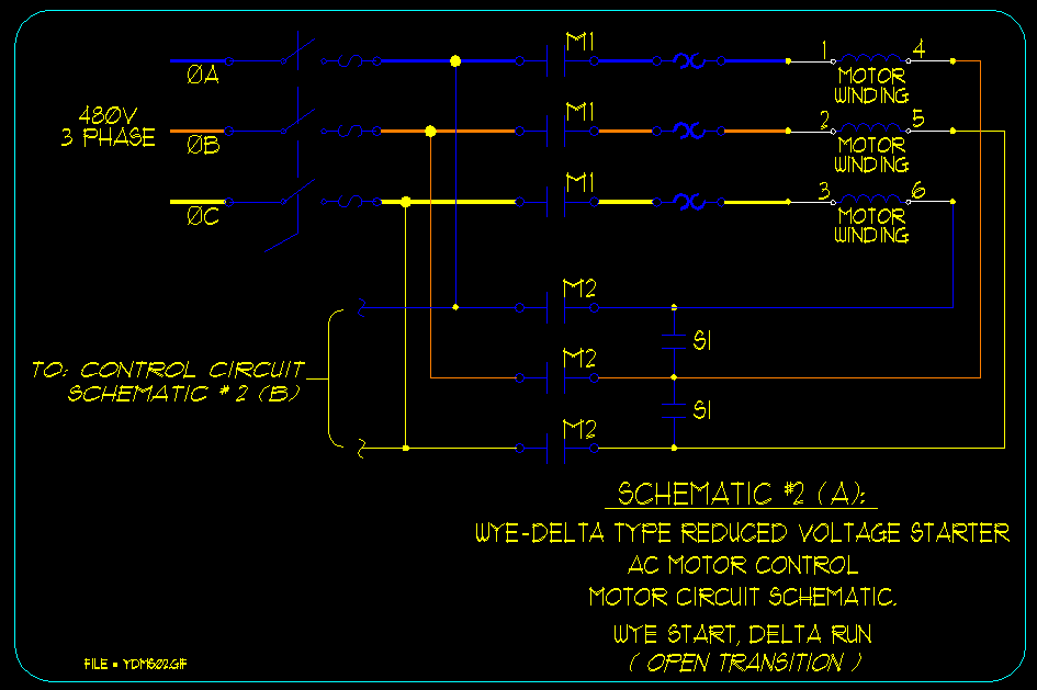
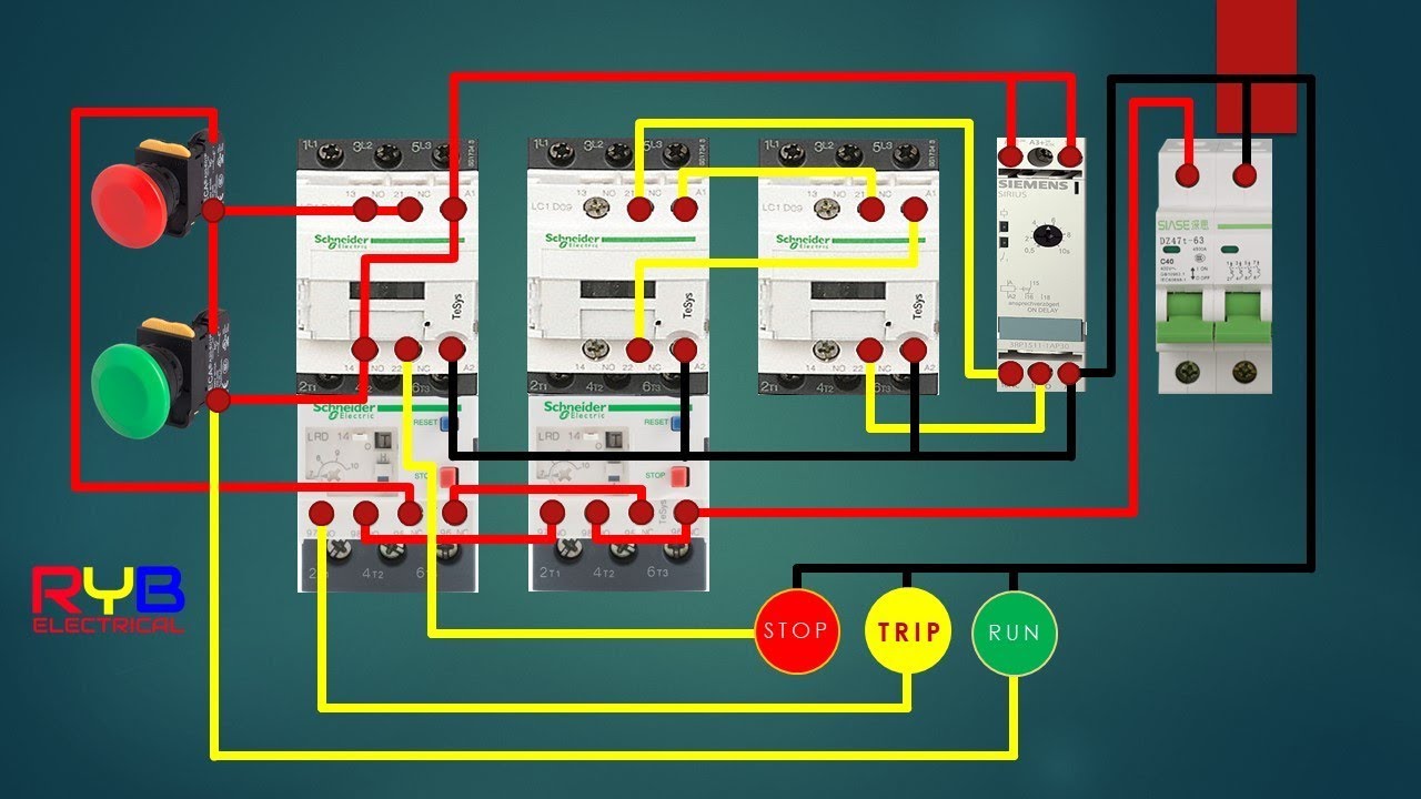
Collection of wye start delta run motor wiring diagram. This configuration of voltage sources is characterized by a common connection point joining one side of each source.

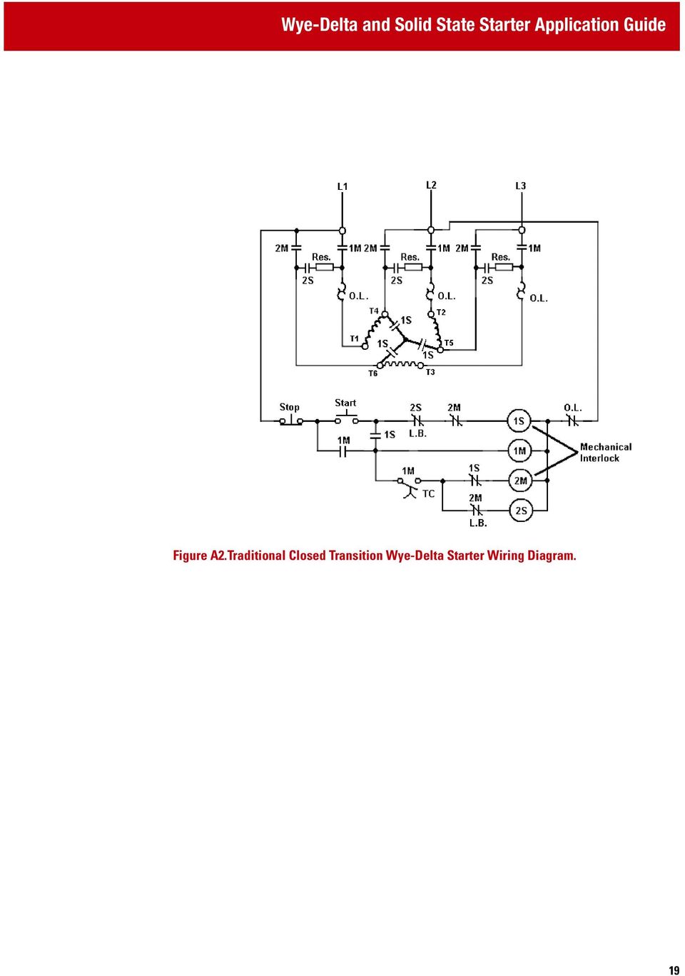
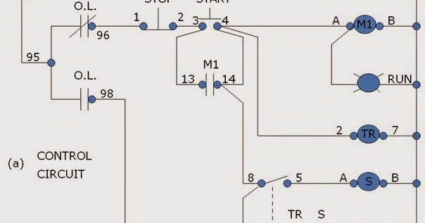
Y Start Delta Run Reduced Voltage Starters Part 1 Of 2
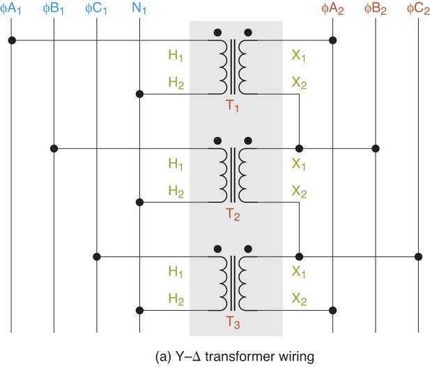
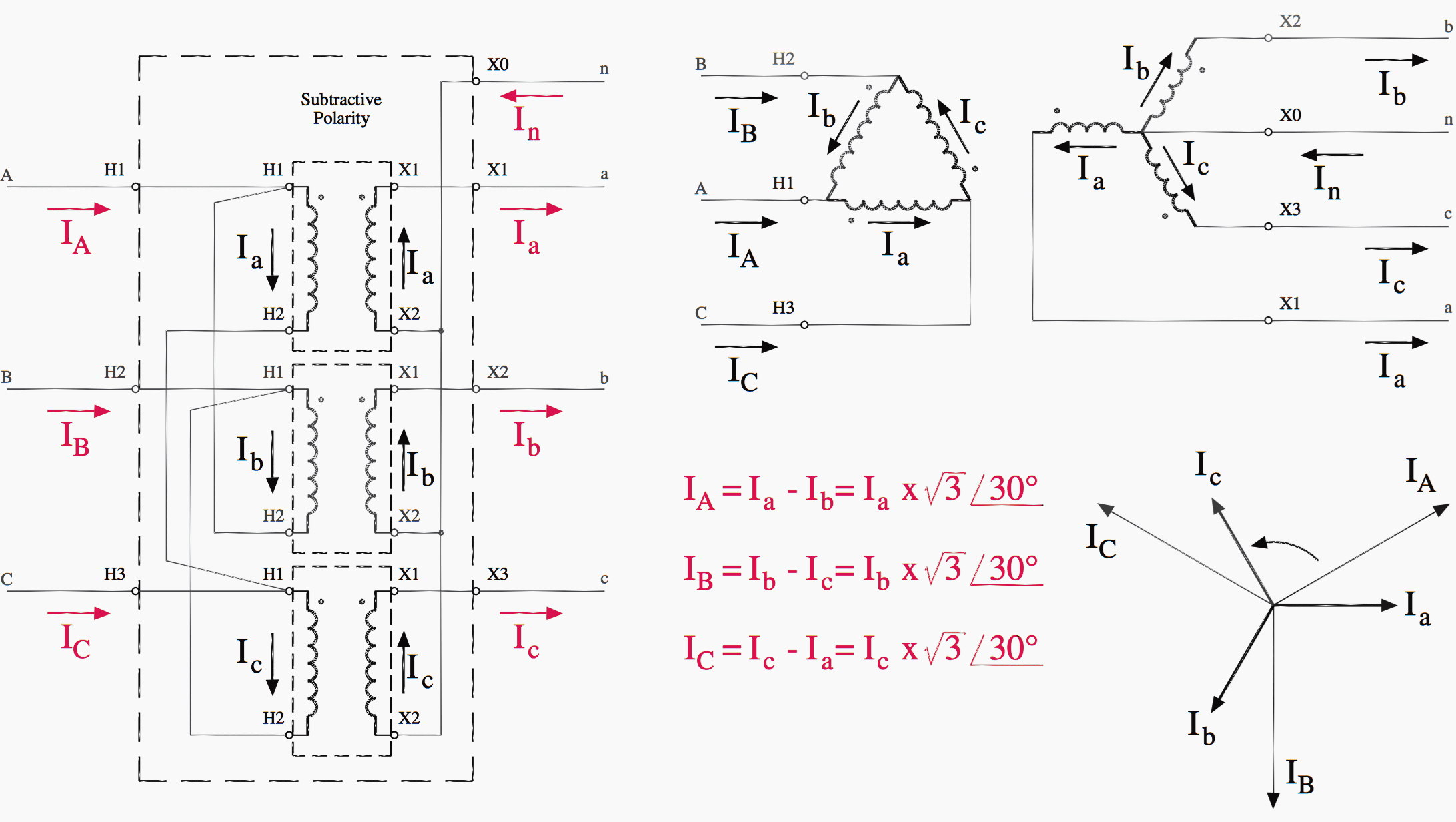
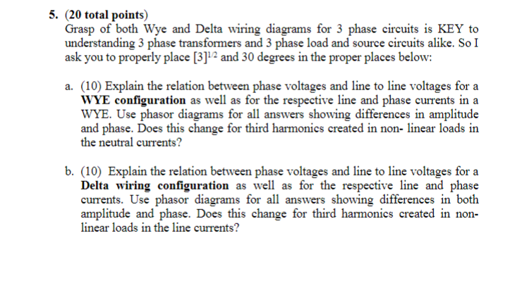
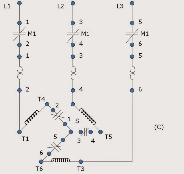
Wye delta wiring diagram. This allows europe to take advantage of the 1732 voltage relationship between the wye and delta connections discussed in part 1 and use them for dual voltage. The wye connected secondary allows single phase load to be distributed among the three phases to neutral instead of being placed all on one winding as with a four wire delta secondary. The most common voltage combinations are 220380v ac and 277480v ac. A wiring diagram is a simplified conventional photographic depiction of an electrical circuit. And connection diagram typically indicate wye delta or star delta but there may also be references to low volts and high volts. A single voltage wye delta motor typically has six leads that are marked t 1 through t 6.
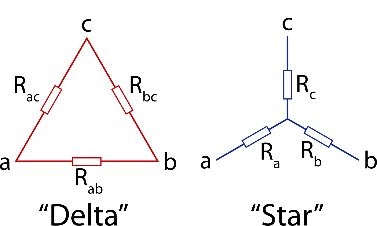
It shows the parts of the circuit as streamlined forms as well as the power as well as signal links between the gadgets. The deltawye connection is the most commonly used three phase transformer connection. The y δ transform also written wye delta and also known by many other names is a mathematical technique to simplify the analysis of an electrical networkthe name derives from the shapes of the circuit diagrams which look respectively like the letter y and the greek capital letter δthis circuit transformation theory was published by arthur edwin kennelly in 1899. In comparison a standard. Initially we explored the idea of three phase power systems by connecting three voltage sources together in what is commonly known as the y or star configuration. In the us the ratio of high and low voltage is 21 460 volts230 volts but in europe it is 31 380 volts220 volts.
Gallery of Wye Delta Wiring Diagram