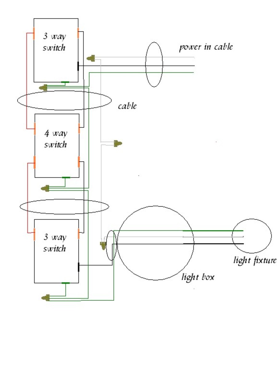
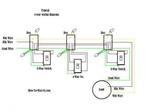
Wiring a 4 way switch is simply adding a switch to an already existing 3 way switch circuit. Four way switch wiring diagrams.

Lutron Three Way Dimmer Switch Wiring Diagram Diagram Base
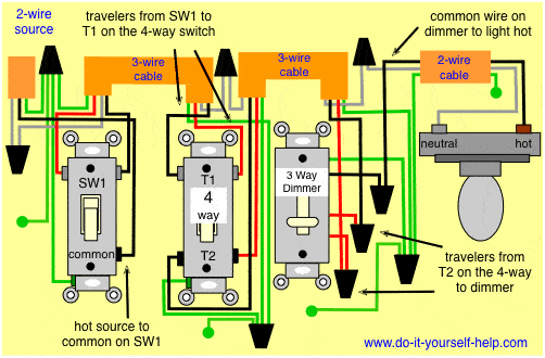
4 way switch wiring diagram power at switch. Two of the terminals are brass and labeled input the other two are black and labeled output. Do you need a 3 way switch wiring diagram. In the 1st diagram below a 2 wire nm cable supplies power from the panel to the first switch box. When wiring a 4 way switch circuit as shown below. 4 way dimmer switch wiring diagram. To make this circuit work a 3 way dimmer can be used in place of one or both of the standard 3 way switches.
First of all we need to go over a little basic terminology on switches. Study the 4 way switch and the manufacturers directions. The load wire is in one 3 way switch box and the line from the power source is in the other 3 way switch box. A 4 way switch is used when you have three or more locations that operate a light or group of lights. The lever does not have an on or off label. It is very important to pay attention to these as shown in the 4 way switch diagram.
Two terminalpoles are labeled in and two are labeled out pairs of wires called travelers will connect to each side. I have a few of the most common ways in wiring a 4 way switch to help you with your basic home wiring projects. The 4 ways are in between. A 4 way switch has 4 terminals or poles. This allows you to control a load from other locations in addition to the 2 locations that a 3 way circuit provides. The black line wire connects to the common terminal of the first 3 way switch.
The 4 way is used when you want to control the light or lights from two or more locations. Three wire cable runs between all the switches and 2 wire cable runs to the light. Click here to access note. This 4 way switch diagram 1 shows the power source starting at the left 3 way switch. Typical 4 way switch wiring nm cable. A 3 wire nm connects the traveler terminals of the first 3 way switch and the first 4 way switch.
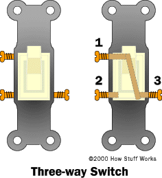
When the switch is operated current will either travel straight through or crisscross. This is the wiring for a dimmer in a 4 way circuit. A 4 way switch is always wired between a pair of 3. 4 way switches can be quickly identified by the 4 screw terminals in addition to the greengnd screw terminal. A 4 way switch wiring diagram is the clearest and easiest way to wire that pesky 4 way switch. Power from light fixture to light switch.
For complete instructions on wiring a basic 4 way switch see our wiring a 4 way switch article. This diagram is a thumbnail. 4 way switch schematics can also be used for intermediate switches. The white wire of the cable going to the switch is attached to the black line in the fixture box using a wirenut. To view it at full size click on the diagram. How to wire a 4 way switch.
This 4 way switch diagram 2 shows the power source starting at the fixture. A typical four way switch wiring diagram.


