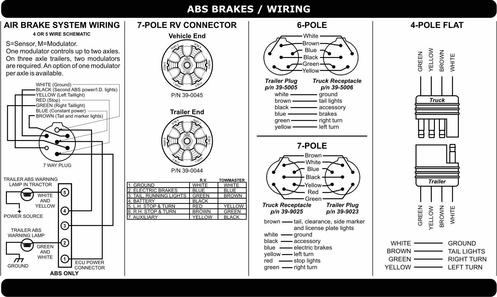
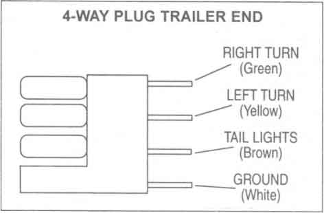
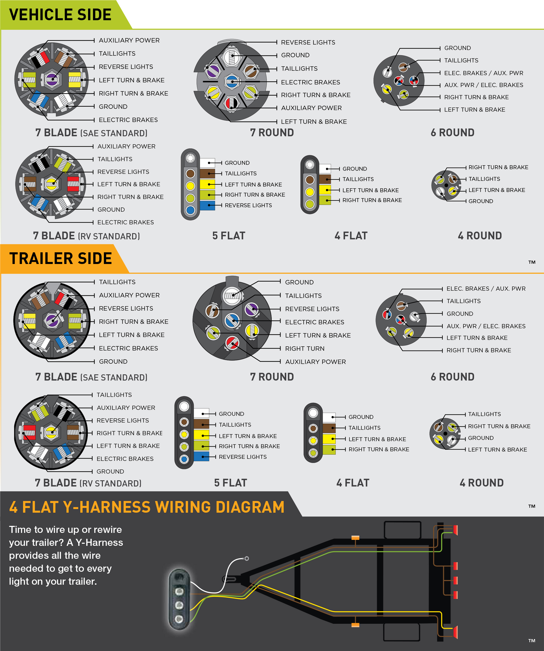
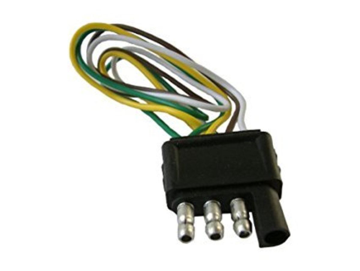
34 inch by 1 inch 6 way rectangle connectors right turn signal green left turn signal yellow taillight brown ground white. The basic purpose remains the same whether your truck and trailer is using a 4 way 5 way 6 way or 7 way connector.

Trailer Wiring Diagram Lights Brakes Routing Wires
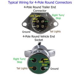
Trailer wiring schematic 4 pin. The first thing you need to do is make sure that your connector works properly. 4 pin trailer light wiring diagram. Installing your 4 pin trailer wiring system is easy if you follow the correct procedure. 4 pin trailer wiring diagram. The ground wire should be run from the frame of the. 1 4 wire the first 4 pins white brown yellow green just like the 4 pin connector above.
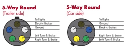
Use on a small motorcycle trailer snowmobile trailer or utility trailer. The circuits are for left and right brake lights and running lights. Make sure that all cables are electrically conductive. Three wires are for the trailer while the last wire is the ground wire. 5 pin trailer wiring diagram download. The red and blue wire can be used for brake control or auxiliary.
Ford trailer plug wiring diagram 2008 ford trailer plug wiring diagram ford f150 trailer plug wiring diagram ford f250 trailer plug wiring diagram people today understand that trailer is a car comprised of very complicated mechanics. This car is designed not just to travel 1 location to another but also to take heavy loads. Running lights left turn signal and brake lights right turn signal and brake lights and ground. Boat trailer wiring diagram trailer wiring junction box diagram. To connect the electric system of your trailer to the vehicle you will be using special connector. Many trailers have three circuits.
A 4 way trailer connector has the basic lighting functions only. 4 way flat trailer wiring diagram pics. Blue electric brakes or hydraulic reverse disable see blue wire notes below in the trailer wiring diagram and connector application chart below use the first 5 pins and ignore the rest. Above we have describes the main types of trailer wiring diagrams. By law trailer lighting must be connected into the tow vehicles wiring system to provide trailer running lights turn signals and brake lights. Can also be used as custom wiring on trailers with 3 lightwire systems.
This article will be discussing ford trailer plug wiring diagram. A 7 way has these functions and a 12 volt circuit a circuit for electric trailer brakes requires a brake controller in the vehicle and a reverse light or auxiliary power circuit. 4 pin connectors are the standard used for most trailers. Trailer electrical connectors come in a variety of shapes and sizes. Traditional trailer with brakes use a 5 pin connector. Below is the generic schematic of how the wiring goes.
5 pin boat trailer wiring diagram collections of wiring diagram for a 7 round trailer plug inspirational 5 pin flat. One way to check for faulty wires is to use a circuit tester. If it is not no amount of wiring will get the lights to work.
