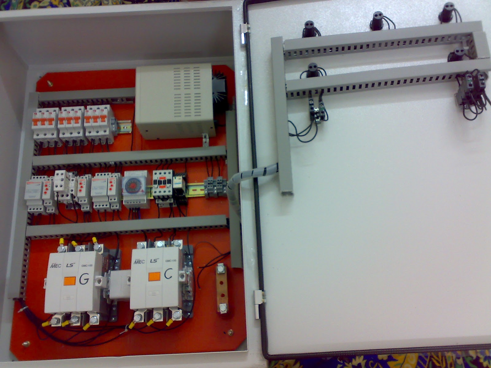
The book describes in simple words and drawings the basic principles to make generator control panels. Panel voltage selectable transformer breaker neutral ground bond control panel for more information visit.

Ats Wiring Diagrams H1 Wiring Diagram
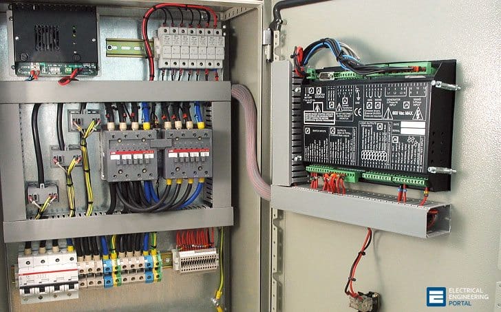
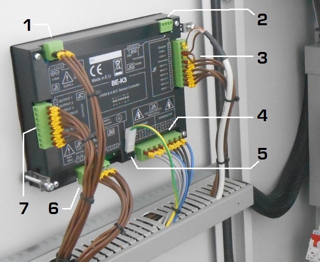
Ats panel circuit diagram pdf. An amf panel equipped with bek3 is designed to work with the power generator engine battery. Automatic transfer switch diagram. May 2018 om manual for 600 1000a 480 vac 3 position open service entrance contactor based transfer switch figure 3. The controller will guarantee remote control monitoring and functionalities when utility power is outside limits. Learn how to make automatic transfer switch panels. Amf control panel circuit diagram pdf description.
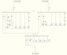
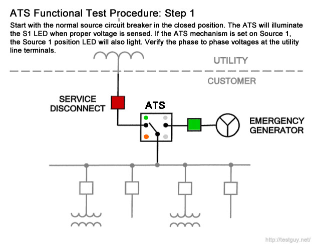
Technical information 3 standard diagrams transfer between 2 sources 1 bus bar. This guide will help you to make by your own generator control panels for standby generator. Typical service entrance open transition ats. Superior design and robust construction make jundi electrical industry teco automatic transfer switch the industry. What others are saying ats panel control is the best option in situation wherever you have to control a power generator that is connected to the mains in a standby configuration. 12 selection the size of automatic transfer switch 13 automatic transfer switch components 14 modes of operation 15 schematic circuit diagram for automatic transfer switch 16 recommended cable size 17 specifications 171 general specification 172 controller specification 18 ordering information 19 detailed drawings.
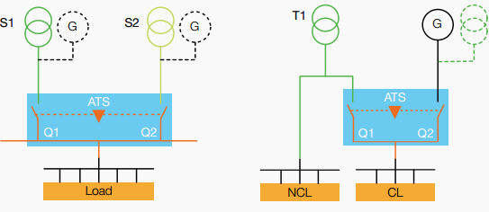
Motorised switch cl ncl g q1 q2 ats automatic transfer switch protection arent shown on the following schemes summary. A distribution board also known as panelboard breaker panel or electric panel is a component of an electricity supply system that divides an electrical power feed into subsidiary circuits while providing a protective fuse or circuit breaker for each circuit in a common enclosure. Electrician circuit drawings and wiring diagrams youth explore trades skills 3 pictorial diagram. You will understand all details by following a step by step 60kva amf panel manufacturing. A diagram that uses lines to represent the wires and symbols to represent components. Breaker contactor or motorised switch socomec diagram.
A diagram that represents the elements of a system using abstract graphic drawings or realistic pictures. The bek3 controller is able to work from 5 up to 36vdc. In the automatic changeover switch for generator circuit diagram the contactors are indicated kg for generator and km for mains. Ats panel wiring diagram pdf. Automatic transfer switch circuit diagram. In our step by step electrical wiring installation tutorials series we will show how to wire and connect single phase and three phase automatic and manual changeover and transfer switches to the home distribution board to use the backup power supply such us batteries power with ups and inverters or generator power in case of emergency breakdown and power outage.
The guide includes step by step examples in a way that you will be able to make panels in the size 15 up to 200kva.
