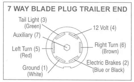
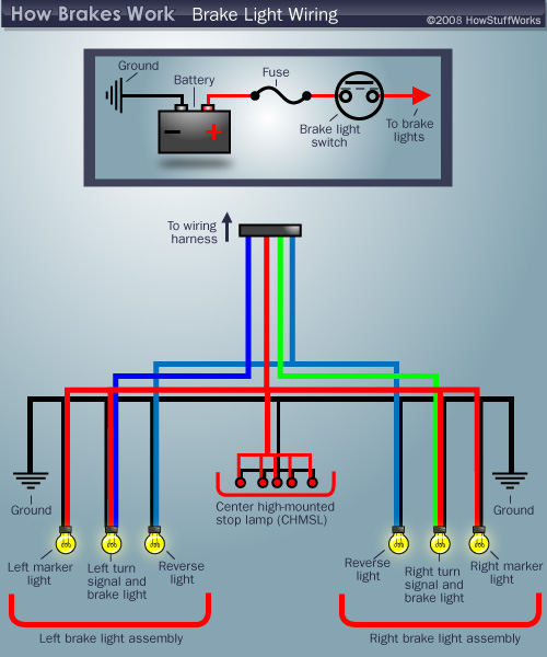
It is referred to as such as the system needs a mere four wires for the trailer tail lights turn signals and brake lights to illuminate. 4 way trailer connectors are typically used on small trailers such as boat snowmobile utility and other trailers that that do not use brakes.

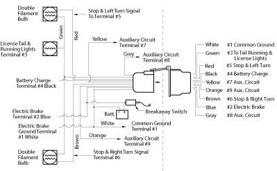
Xk 2914 Trailer Plug Wiring Diagram Electric Brakes Download
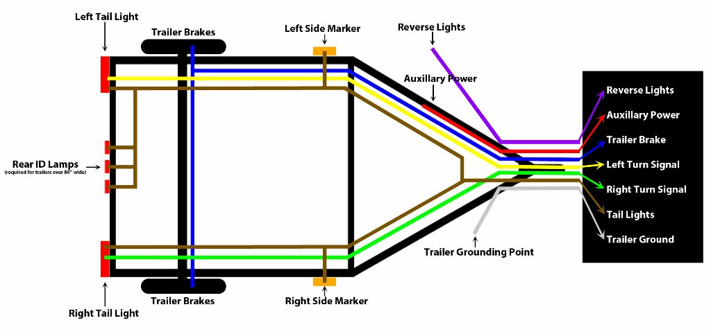
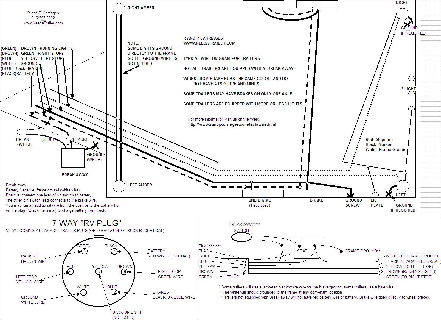
Trailer light and brake wiring diagram. Though trailer lighting systems are available in an array of configurations the most popular is the 4 way system. 4 way trailer connectors are. Trailer wiring diagrams trailer wiring connectors. It reveals the parts of the circuit as streamlined forms as well as the power and signal connections in between the gadgets. Assortment of electric trailer brake wiring schematic. The four wires control the turn signals brake lights and taillights or running lights.
A wiring diagram is a streamlined conventional pictorial representation of an electric circuit. As the name implies they use four wires to carry out the vital lighting functions. Please see the trailer wiring diagram and connector application chart below. 5 wire trailer wiring diagram. The 4 way system is designed so the right brake light wire and right turn signal are green. 5 way trailer wiring diagram allows basic hookup of the trailer and allows using 3 main lighting functions and 1 extra function that depends on the vehicle.
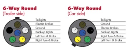
They also provide a wire for a ground connection. Various connectors are available from four to seven pins that allow for the transfer of power for the lighting as well as auxiliary functions such as an electric trailer brake controller backup lights or a 12v power supply for a winch or interior trailer lights. The rest you can ignore. The 4 pin connector only has the first 4 items listed. An extra pin allows using another extra function. Yellow left turn signal left brake light 4.
Green right turn signal right brake light.
