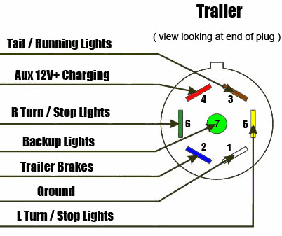
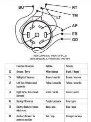
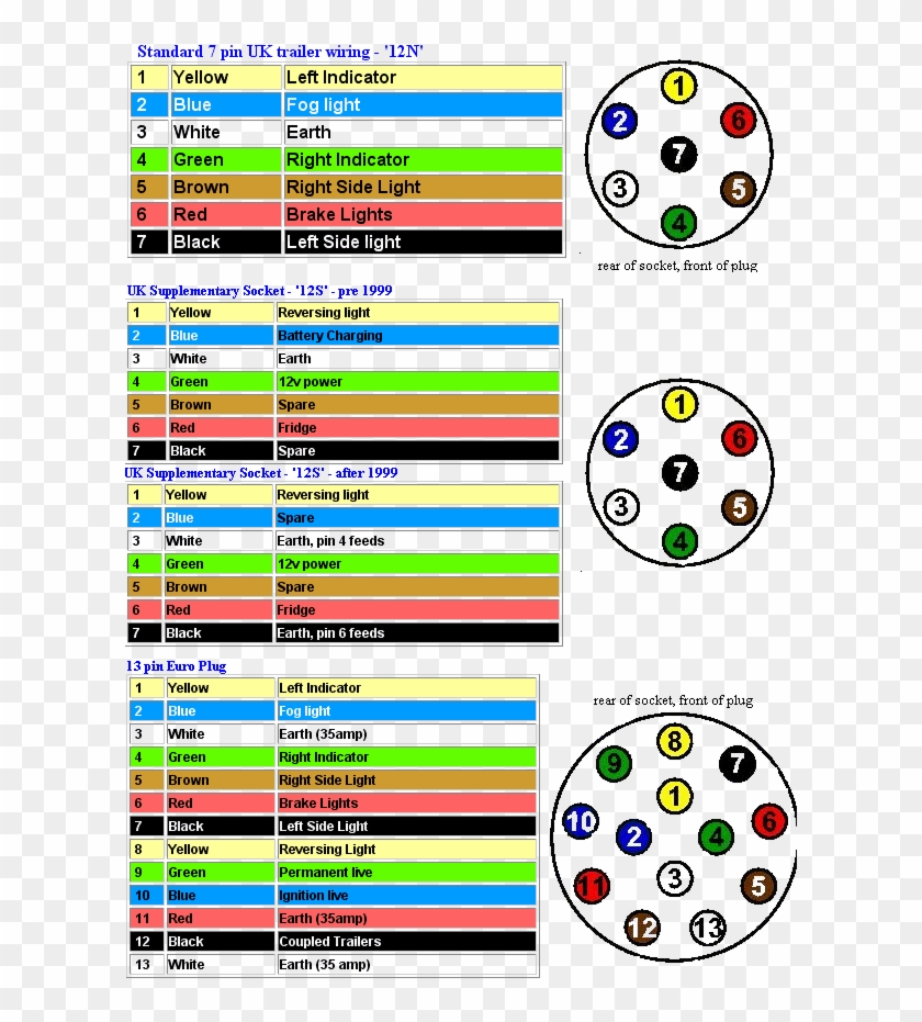
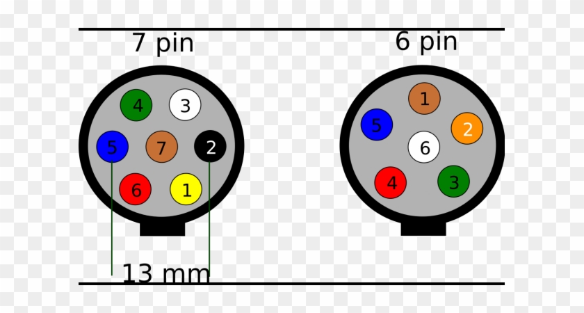
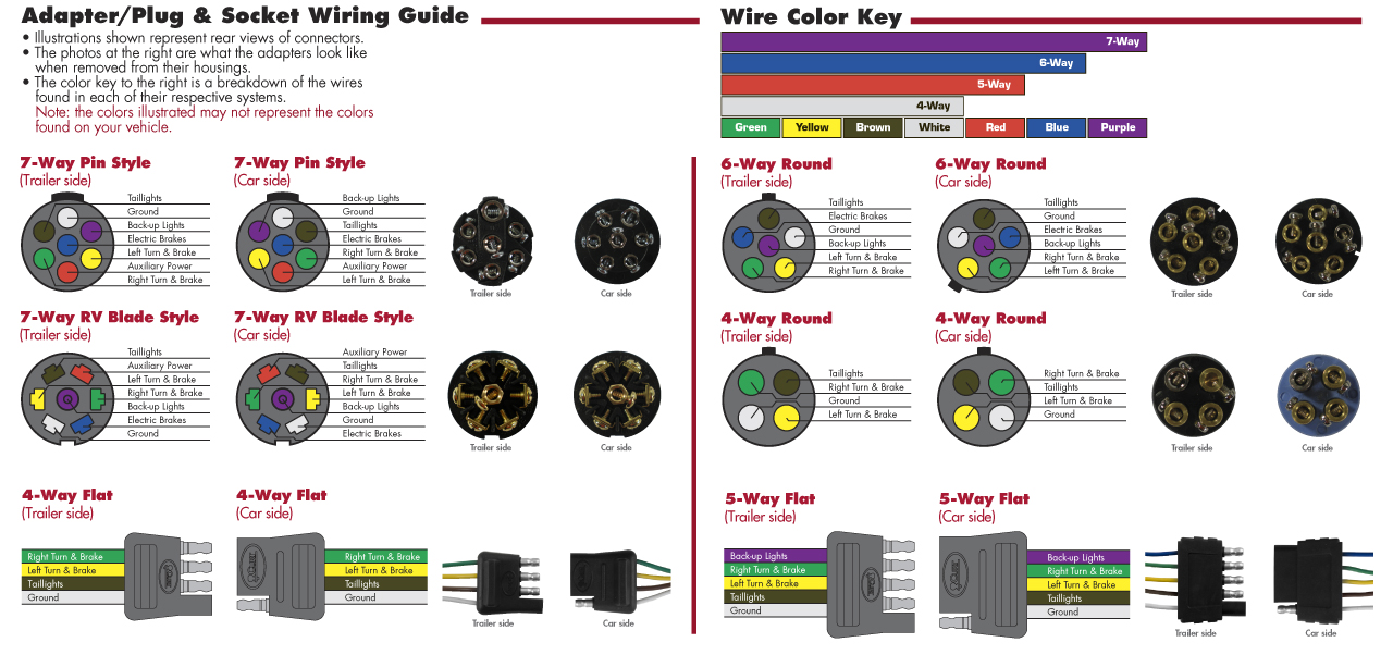
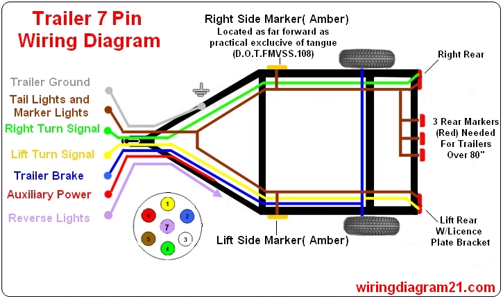
Below is the generic schematic of how the wiring goes. When wiring a trailer connector it is best to wire by function as wire colors can vary.

Trailer Plug Wiring Diagram 7 Way Flat Diagram Base Website
Trailer receptacle wiring diagram. Use this handy trailer wiring diagram for a quick reference for various electrical connections for trailers. Trailer wiring diagrams trailer wiring connectors. We have an excellent wiring diagram on our website i will provide you a link so you can look at it. In the trailer wiring diagram and connector application chart below use the first 5 pins and ignore the rest. The 30 amp receptacle will need to be wired to a 30 amp single pole gfci breaker in the panel box. To connect the electric system of your trailer to the vehicle you will be using special connector.
4 pin trailer wiring diagram. This will provide 125 volts to the travel trailer receptacle. If your truck has a built in 7 pin socket but you only need 5 of the pins. This automobile is designed not just to travel one place to another but also to carry heavy loads. Trailer wiring diagram wiring diagrams for trailers international 1 989 755 0561 toll free 1 800 358 4751 covid 19. Due to its four prong receptacle the 50 amp socket provides significantly more power.
If your vehicle is not equipped with a working trailer wiring harness there are a number of different solutions to provide the perfect fit for your specific vehicle. Two of the prongs supply 120 volts each and both of them deliver 50 amps. Above we have describes the main types of trailer wiring diagrams. View our rv wiring diagram to understand how an rv electrical system works and the diference between ac and dc power. Use the 7 pin connector anyway see below and just leave out the last 2 wires. Using the same formula amps50 50 x.
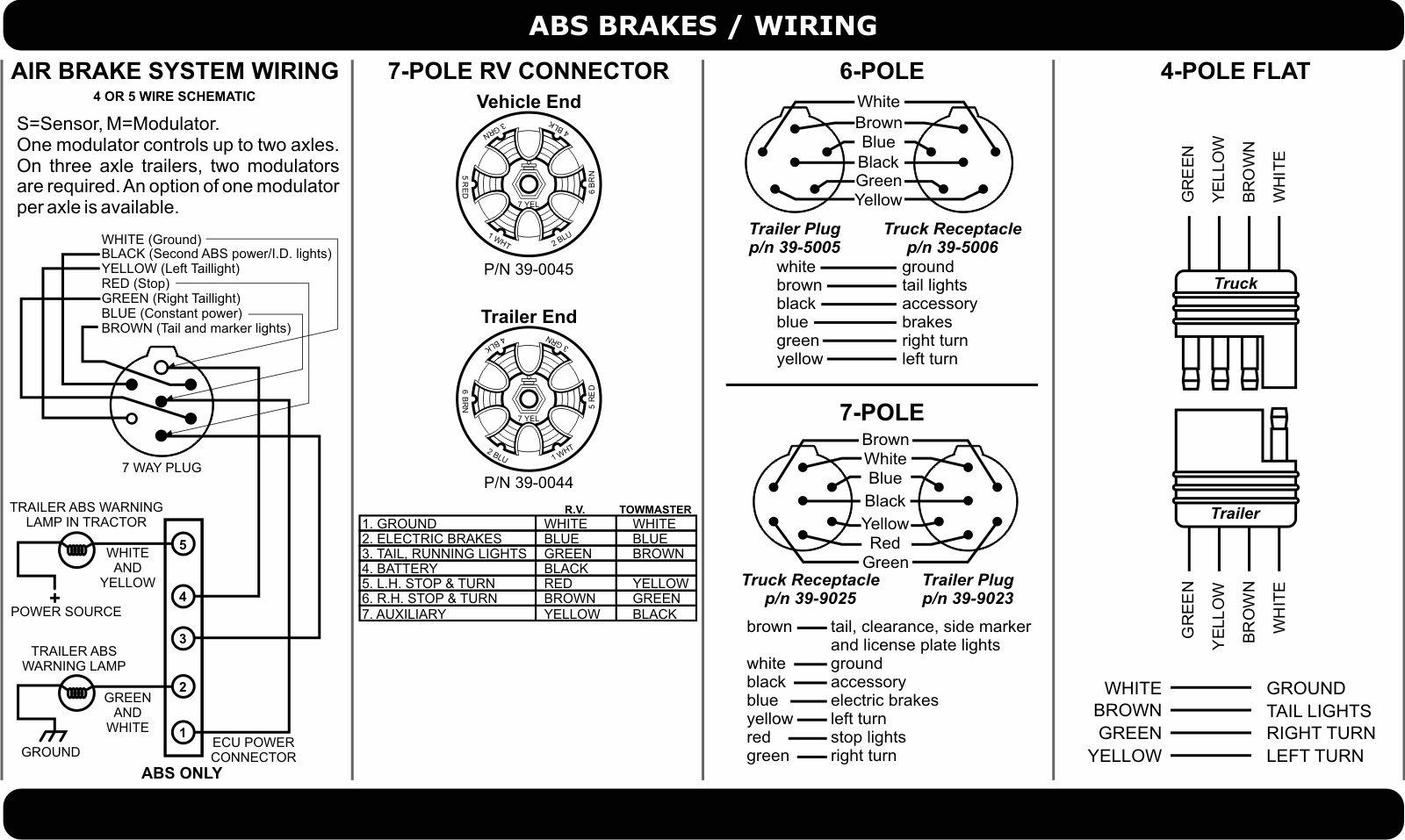
Wiring diagram for 7 prong trailer plug wiring diagram for 7 pin trailer connector wiring diagram for 7 pin trailer plug wiring diagram for 7 pin trailer plug australia people understand that trailer is a vehicle comprised of quite complicated mechanisms. Various connectors are available from four to seven pins that allow for the transfer of power for the lighting as well as auxiliary functions such as an electric trailer brake controller backup lights or a 12v power supply for a winch or interior trailer lights. The national electric code nec states that any outside receptacle must be ground fault circuit interrupter gfci subsequently you must install a gfci receptacle or a gfci breaker. If you are looking at the inside of the trailer connector where the wires mount to the terminals starting at the top and rotating clockwise. Complete with a color coded trailer wiring diagram for each plug type this guide walks through various trailer wiring installation solution including custom wiring splice in wiring and replacement wiring.

