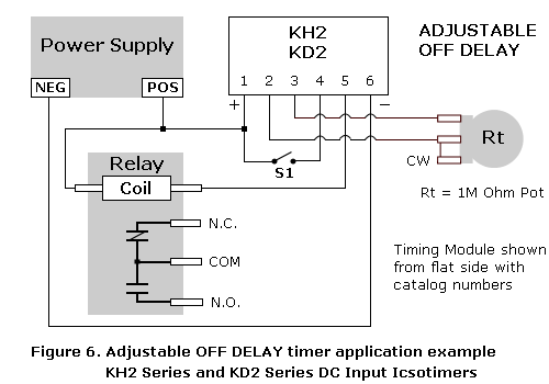
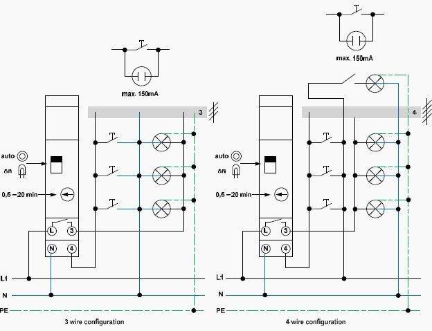
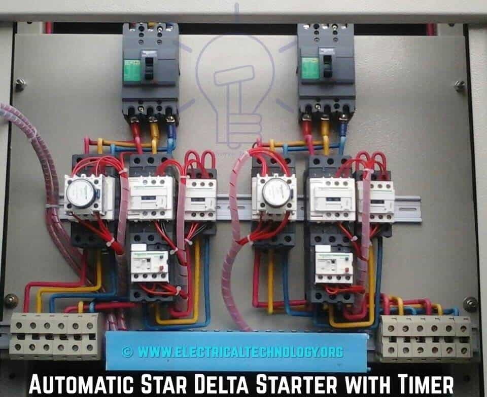
In the above star delta starter control circuit wiring diagram with timer and normally close push buttonnormally open push button switch. In control wiring diagram all magnetic contactors coils are rated 220 vac.

Timer Connection Diagram Youtube
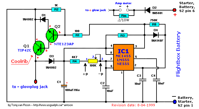
Timer connection diagram. High capacity off grid solar generator rev 4 wiring diagram parts list design worksheet duration. A wiring diagram is typically utilized to troubleshoot issues and making certain that each of the links have actually been made and that every small thing exists. Let us discuss in detail about this circuit. Video on long duration timer circuit diagram. The delay pulse is obtained at ic 4060. The hot wire connections for a mechanical timer switch include both a line and load connection.
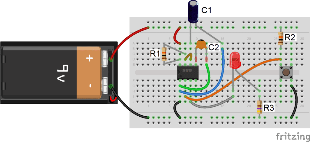
These on off intervals can be adjusted by varying the 555 timer output and number of counter outputs. The counter output is set by a jumper. Adjustable on off timerusing 555 astable mode in this circuit a timer with cyclic on off operations is designed. Direct online starter animation diagram. The on delay timer diagram is also shown in the diagram. This circuit uses very basic components like 555 timer and 4017 counter.
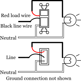
The diagram could be mailed or e mailed. A 8 pin timer are used. The ic4060 is a 14 stage binary ripple counter which generates the basic time delay pulses. The wiring diagram is not suitable for the kenmore 11020072993. Desert prep recommended for you. The line connection is where the incoming hot wire from the power source is connected while the load connection carries power onward from the switch to the appliance or device.
Variable resistor r1 can be adjusted to get different time delays.


