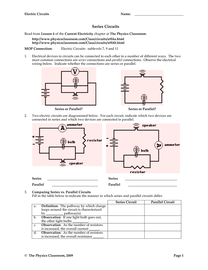
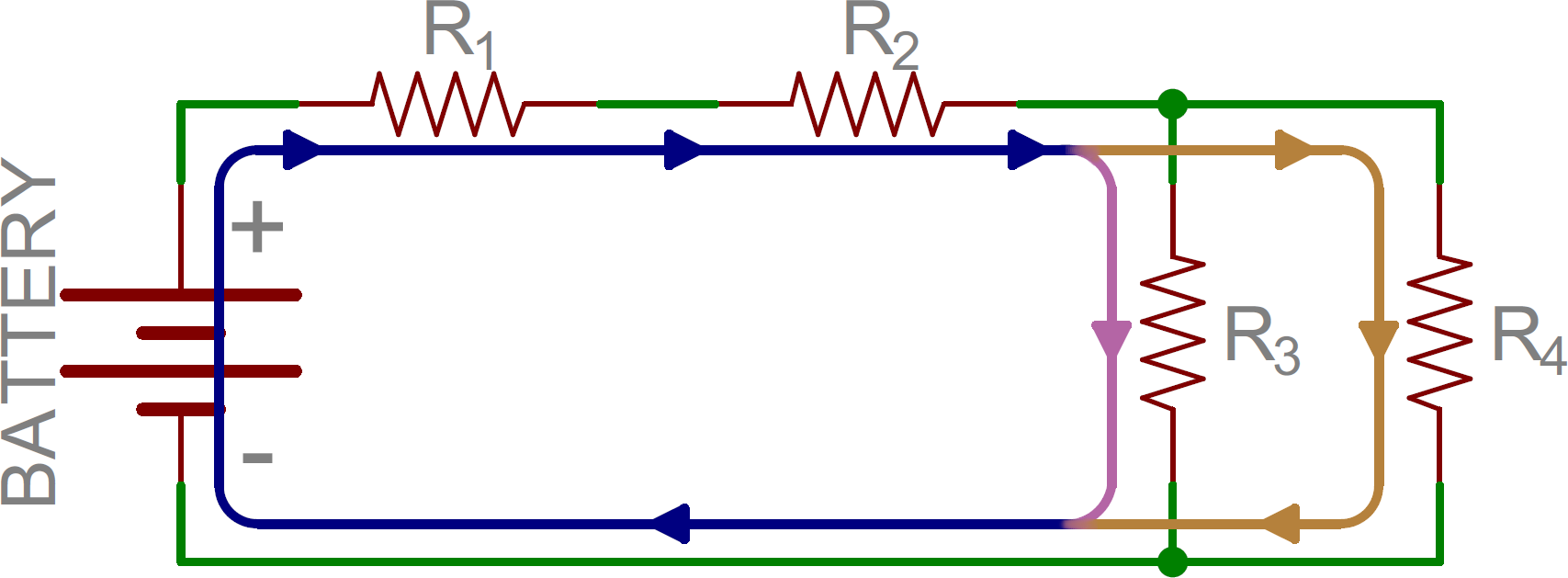
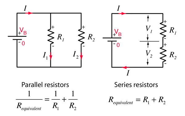
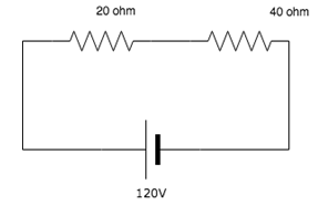
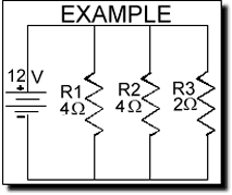
There are two basic ways in which to connect more than two circuit components. Connection solar panels in series diagram the calculation of solar panels is just like batteries series calculation in solar panels wiring in series the v voltage will be plus or in cress and the amps amperes will be same.
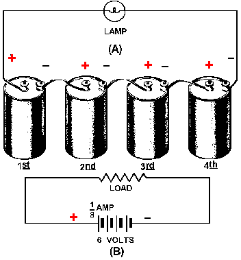
Series Connected Cells
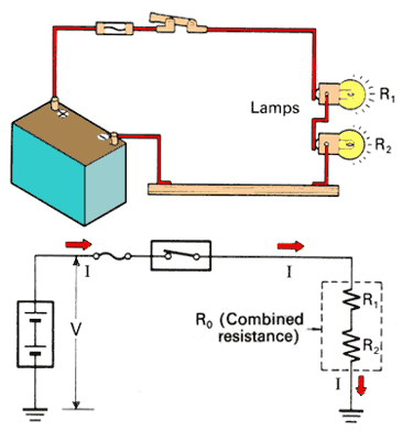
Electrical series connection diagram. First an example of a series circuit. We can use it for short circuit test. 64 plastic board 1 piece 2. First i want to show how to wire lights in series connection in simple words a series circuit is a circuit in which we have only one path for current flow and only one way to flow the electron. In the above diagram i shown how to wire lights in parallel with supply but one thing more that we mostly use the parallel connection in house wiring and other electrical wiring installation. There are many advantage and uses of series board which some are below.
A wiring diagram is a simple visual representation of the physical connections and physical layout of an electrical system or circuit. We can make this board any time with in a small time. Components of an electrical circuit or electronic circuit can be connected in series parallel or series parallel. It should be. In electrical and electronics engineering it is very important to know the differences between series and parallel circuits. 100 watt bulb 1 piece 7.
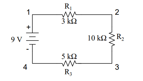
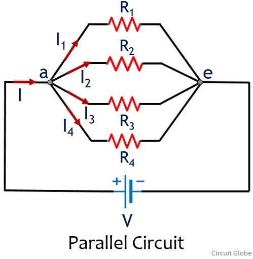
Here we have three resistors labeled r 1 r 2 and r 3 connected in a long chain from one terminal of the battery to the other. The two simplest of these are called series and parallel and occur frequently. They are the two most basic forms of electrical circuit and the other one being the series parallel circuit which is the combination of both can be understood by applying the same rules. The wiring of lights or lamps in parallel connection is too simple you need to provide neutral and phase hot wire to each light bulb or lamp. We can use it for connectivity test. Fuse 1 piece 4.
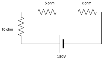
Components connected in series are connected along a single conductive path so the same current flows through all of the components but voltage is dropped lost across each of the resistances. Series and parallel circuits. Wiring lights in series connection diagram current and voltage in series circuit. It shows how the electrical wires are interconnected and can also show where fixtures and components may be connected to the system. We can do connection of a 3 phase motor in start delta. Batten holder 1 piece 6.
Key differences between series and parallel circuits. Although we know that series connection for household wiring like fans switches light bulbs etc is not a preferred way instead of parallel or series parallel wiring. Two pin socket 2 piece 3. We can find out the shortage in any electrical appliances. But in some case we need to wire and connect electrical appliances in series as well. Switch 1 piece 5.
For example if you wire two 12 volts 6 amperes solar panel in series with one another then you complete out put will be.
