A wiring diagram is a simplified standard pictorial depiction of an electrical circuit. Single phase motor dol starter connection diagram.

Single Phase Motor Starter With Timer Diagram Single Phase
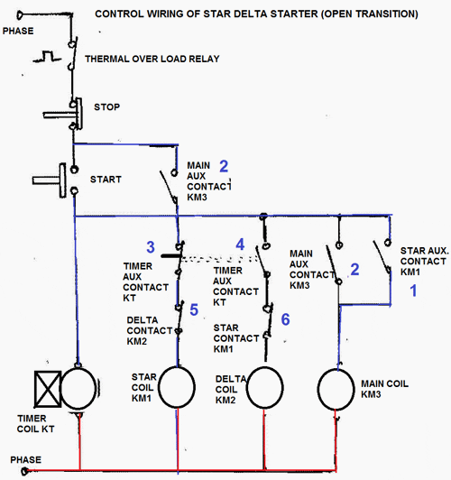
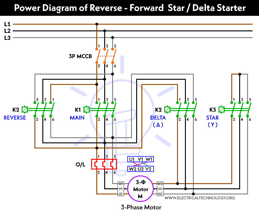
Single phase timer connection diagram. The three phase supply shown with red yellow and blue coolers all connection with a 3 phase induction motor. Wikipedia single phase induction motors. Star delta starter wring for 3 phase motor diagram here i shown the complete star delta starter wiring diagram 3 phase. Assortment of single phase submersible pump starter wiring diagram. You can also connect timer limit switches float switch reverse forward remote switches and other controlling device. Note that the single phase dol starter wiring diagram is also like this.
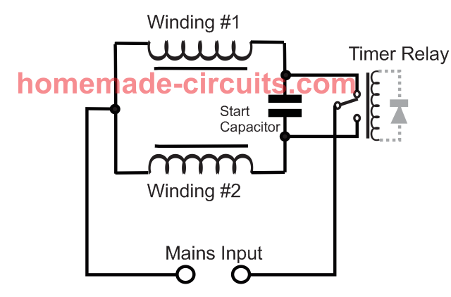
Thermal magnetic single phase 3 phase squirrel cage 2. And if you want to learn about the dol starter wiring for single phase then read the below post. A simple circuit diagram either of the two start buttons will close the contactor either of the stop buttons will open the contactor. With single phase motor with capacitor forward and reverse wiring. Single phase motor wiring diagram forward reverse collections of phase meter wiring diagram single phase motor capacitor wiring. In the above one phase motor wiring i first connect a 2 pole circuit breaker and after that i connect the supply to motor starter and then i do cont actor coil wiring with normally close push button switch and normally open push button switch and in last i do connection between capacitor.
When a 1 phase supply is connected to the stator winding a pulsating magnetic. Single phase induction motors. Single phase motor wiring diagram with capacitor sources. Three phase induction motor image courtesy. It reveals the elements of the circuit as streamlined forms and also the power and signal links in between the gadgets. A single phase induction motor consists of a single phase winding on the stator and a cage winding on the rotor.
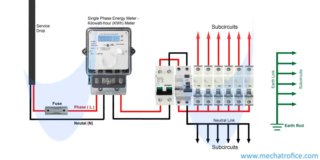
Wiring diagram for single phase motor fresh pretty single phase. The above diagram is a complete method of single phase motor wiring with circuit breaker and contactor. A large percentage of the motors using industry are a single phase and three phase motors as seen in figure 2. Wiring diagram book a1 15 b1 b2 16 18 b3 a2 b1 b3 15 supply voltage 16 18 l m h 2 levels b2 l1 f u 1 460 v f u 2 l2 l3 gnd h1 h3 h2 h4 f u 3 x1a f u 4 f u 5 x2a r power on optional x1 x2115 v 230 v h1 h3 h2 h4 optional connection electrostatically. A single phase induction motor is an electric motor that operates on a single waveform of alternating current. Mar 14 2017 single phase motor contactor wiring diagram elec eng world.
Note that one one of the contactor acts as a switch for the start button. Control and power connection table 4.


