The diagram symbols in table 1 are used by square d and where applicable conform to nema national electrical manufacturers a ssociation. Why 3 phase ac instead of single phase.

Using 3 Pole Contactor With Single Phase Electrical Diy
Single phase contactor diagram. Wiring a single phase motor through a 3 phase contactor. In the above one phase motor wiring i first connect a 2 pole circuit breaker and after that i connect the supply to motor starter and then i do cont actor coil wiring with normally close push button switch and normally open push button switch and in last i do connection between capacitor. Single phase reversing contactor wiring diagram. The contactor will have space for the red power wires coming in from the photocell circuit breaker and lights. How do i do a wiring to a single phase contactor via photocell to the outside lights. In the above one phase motor wiring i first connect a 2 pole circuit breaker and after that i connect the supply to motor starter and then i do cont actor coil wiring with normally close push button switch and normally open push button switch and in last i do connection between capacitor.
Home about us news wiring a single phase motor through a 3 phase contactor. The black power wires will need to be tied together. Contactor breakers limit switch no static control. Single phase motor starter circuit. Posted january 18 2018 by springercontrols. Or by calling 888 226 4917.
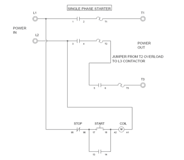
This diagram is for single phase motor control. It uses a contactor an overload relay one auxiliary contact block a normally open start pushbutton a normally closed stop pushbutton and a power supply with a fuse. Wiring diagram components size. Properly connect a single phase motors to a three phase starter. The above diagram is a complete method of single phase motor wiring with circuit breaker and contactor. The lights connect to the output ports on the contactor.
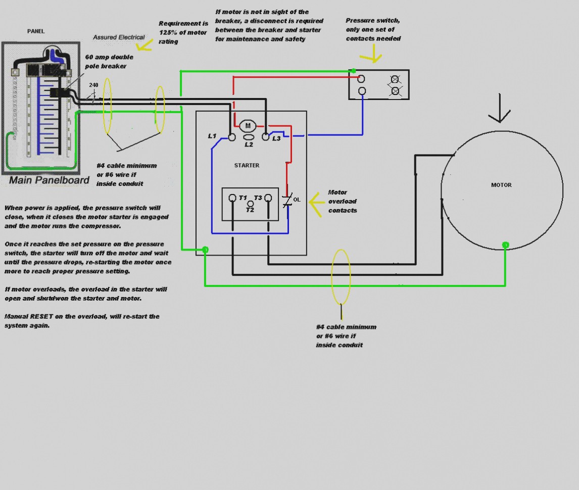
Single phase dwelling services101 table 12 awg and metric wire data 102. 800 x 600 px source. Single phase power is typically reserved for lower power requirements however in some cases powering a small motor with single phase input power is practical. Below are several of the top illustrations we get from numerous sources we hope these images will serve to you as well as with any luck really pertinent to what you desire concerning the wiring diagram single phase motor contactor is. The single phase contactor is sized according to the electric motor voltage and amperage and the control circuit is designed for the specific type of devices that will be used to control the single phase motor. If your motor has three.
The control circuit is typically a lower voltage than the motor voltage. The start and stop circuits could alternatively be controlled using a plc.


