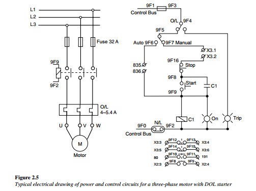
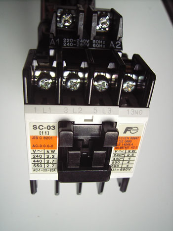
Wiring diagram since wiring connections and terminal markings are. When a 1 phase supply is connected to the stator winding a pulsating magnetic.

What Is Contactor All You Need To Know About Contractors 2020
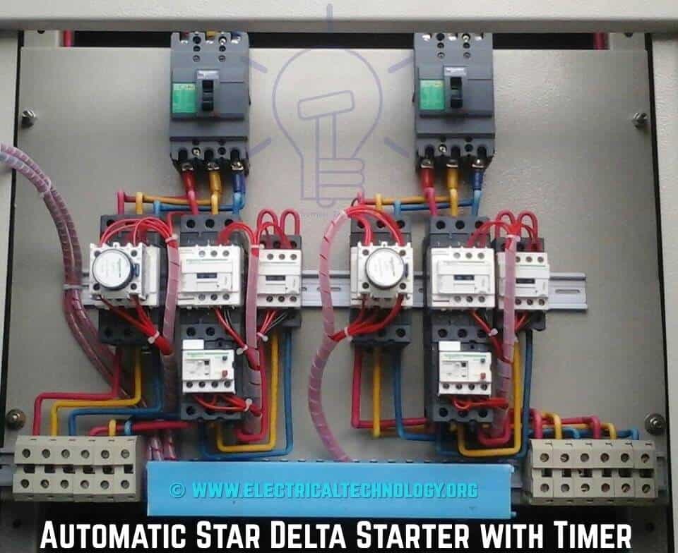
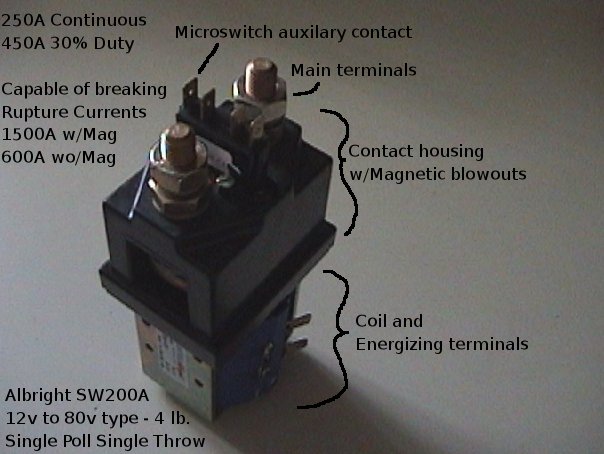
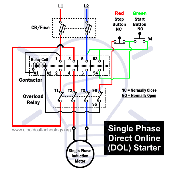
Single phase contactor wiring diagram with timer. A single phase induction motor consists of a single phase winding on the stator and a cage winding on the rotor. Air conditioner contactor wiring diagram inspirationa wiring diagram. The above diagram is a complete method of single phase motor wiring with circuit breaker and contactor. 4 table 2 nema and iec terminal markings. The contactor will have space for the red power wires coming in from the photocell circuit breaker and lights. In this video shows how to connection wiring diagram low current timer switch controls high current load.
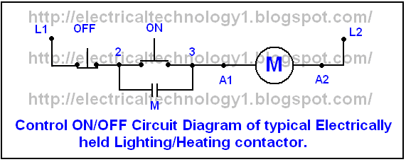
Contactor wiring diagram a1 a2. Mar 14 2017 single phase motor contactor wiring diagram elec eng world. In the above one phase motor wiring i first connect a 2 pole circuit breaker and after that i connect the supply to motor starter and then i do cont actor coil wiring with normally close push button switch and normally open push button switch and in last i do connection between capacitor. With this kind of an illustrative guidebook you will be capable of troubleshoot prevent and complete your projects without difficulty. A simple circuit diagram either of the two start buttons will close the contactor either of the stop buttons will open the contactor. Reversing contactor wiring diagram wiring diagram 12 3 wiring.
The lights connect to the output ports on the contactor. Wiring diagram single phase motor contactor off on switches control connection. Note that one one of the contactor acts as a switch for the start button. How do i do a wiring to a single phase contactor via photocell to the outside lights. 2 pole contactor wiring diagram gallery. Single pole contactor wiring diagram collections of wiring diagram kontaktor best circuit diagram contactor new.
Contactor wiring diagram you will want a comprehensive professional and easy to know wiring diagram. The black power wires will need to be tied together. Contactor breakers limit switch no static control standard elementary diagram symbols. How to wire an air conditioner for control 5 wires the diagram below includes the typical control wiring for a conventional central air conditioning systemfurthermore it includes a thermostat a condenser and an air handler with a heat source. Single phase dwelling services101 table 12 awg and metric wire data 102.

