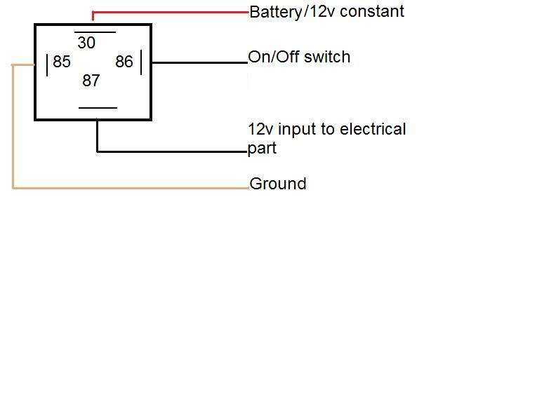
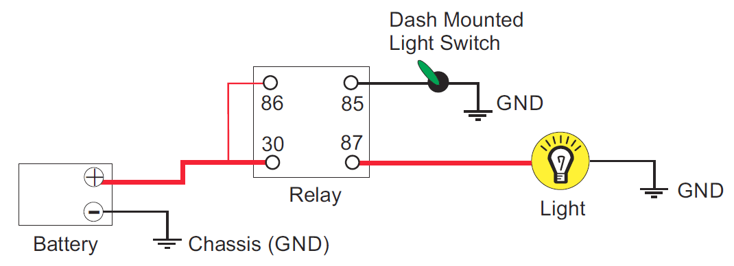
In the above circuit 5v relay is powered by a 9v battery. Diagrams will show how multiple relays one relay or another or just one relay can control your device.

How To Use A Relay Buildcircuit Com
Simple relay wiring diagram. Theyre ready for transfer if you love and wish to take. Color laminated wiring schematics and diagrams for restoring and maintaining classic amc american motors buick cadillac chevy chrysler dodge ford griffith jaguar mercury oldsmobile opel plymouth pontiac studebaker triumph volvo cars and trucks. So if you would like have all of these awesome shots about simple shovelhead wiring diagram new click save link to download the pictures in your pc. This page demonstrates several simple ways to wire a relay for various applications. Here arduino plays a key role in setting this time period. A wiring diagram is a simplified traditional pictorial depiction of an electrical circuit.
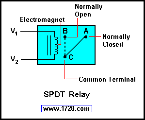
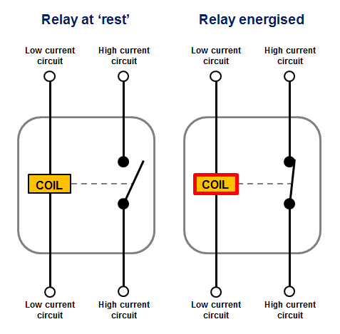
At the initial condition when switch is open no current flow through coil hence common port of relay is connected to no normally open pin so the. The square relay pinout shows how the relay socket is configured for wiring. Dozens of the most popular 12v relay wiring diagrams created for our site and members all in one place. If you need a relay diagram that is not included in the 76 relay wiring diagrams shown below please search our forums or post a request for a new relay diagram in our relay forum. Arduino adjustable timer is simple circuit to generate timer for required time. Relay switch circuit diagram working of the basic 5v relay circuit.
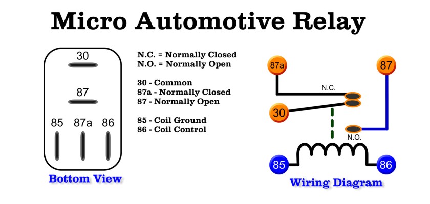
This pinout image is only a 2 pole diagram for room on the page purposes but you can get the picture here with this one since a 3 pole will just have 1 more set of contacts. 17 suzuki motorcycle wiring diagram motorcycle diagram in 2020. An onoff switch is added for the switching purpose of the relay. All examples shown are for spdt single pole double throw relays which includes any of the 5 10 or 20 amp relays on this site. Instructions for wiring a standard automotive relay with descriptions of the pin out and the schematic. Here a relay is used to switch the load for certain amount of time.
It reveals the components of the circuit as simplified shapes and also the power and signal connections in between the tools. This is used to switch on the loads for the certain time period and then they are automatically switched off. Assortment of 12 volt relay wiring diagram. I go over what each contact of the relay is for and how to understand the schematic that is.


