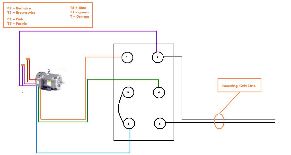
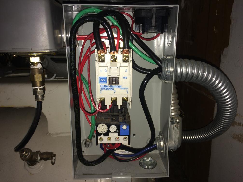
The above diagram is a complete method of single phase motor wiring with circuit breaker and contactor. I hope after watching the above single phase submersible pump starter wiring diagram guide video tutorial i hope now you will fully understood the complete submersible pump control starter wiring diagram or installation and now you will be able to wire or make your own submersible pump motor starter however now if you have any question regarding the video tutorial or diagram then you can ask.

Single Phase Starter Wiring Diagram Diagram Base Website
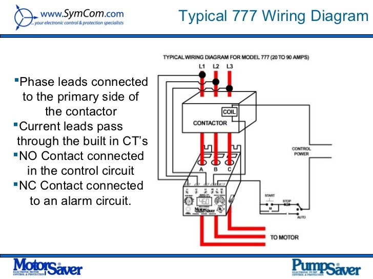
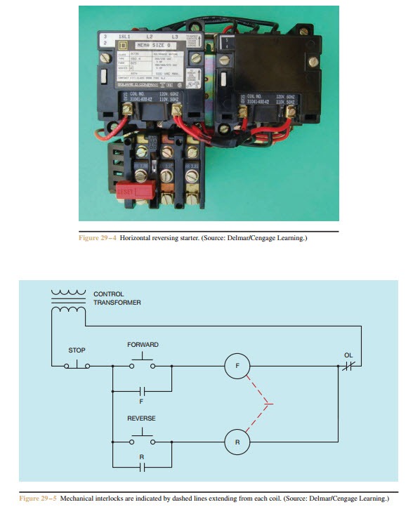
Single phase starter wiring diagram. We hope this helps further your understanding of motor controls. In the above one phase motor wiring i first connect a 2 pole circuit breaker and after that i connect the supply to motor starter and then i do cont actor coil wiring with normally close push button switch and normally open push button switch and in last i do connection between capacitor. It uses a contactor an overload relay one auxiliary contact block a normally open start pushbutton a normally closed stop pushbutton and a power supply with a fuse. A single phase dol motor starter can be designed using the same components as shown in following diagram. The start and stop circuits could alternatively be controlled using a plc. It reveals the parts of the circuit as simplified shapes and the power and signal links between the gadgets.
Collection of single phase motor starter wiring diagram. This diagram is for single phase motor control. Single phase dol starter wiring diagram. The below wiring diagram shows how we would assemble a complete motor starter with a startstop button for a single phase motor utilizing a 3 pole contactor. We have to use all 3 poles of the overload relay otherwise the imbalance due to the current flow in only 2 of them will cause unnecessary tripping. A wiring diagram is a simplified traditional photographic representation of an electric circuit.


