Piping and instrumentation design. Plcs can range from small modular devices with tens of inputs and outputs.

How To Convert A Basic Wiring Diagram To A Plc Program Youtube
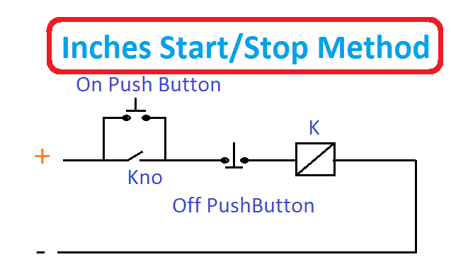
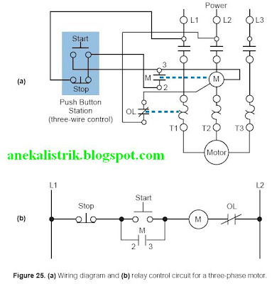
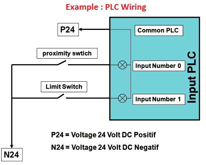
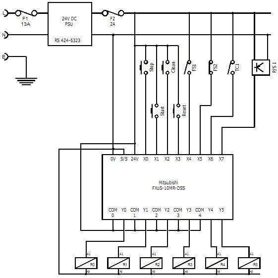
Plc electrical diagram. Just like on the diagram we start with the stop push button. Parts and assembly drawing. The smart thing about ladder logic is that it looks very similar to electrical relay circuits. All critical safety functions should be hardwired this way. One of the best visual programming languages is a plc programming language. This is a continuation of the previous article introduction to plc ladder programming in plc programming seriesplease go through an introduction to ladder programming before reading this post.
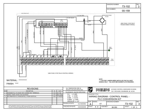
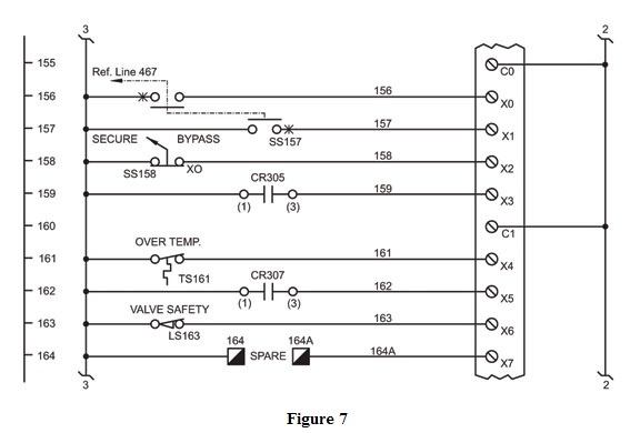
Figure 5 below shows a schematic diagram for a plc based motor control system similar to the previous motor control example. This figure shows the e stop wired to cutoff power to all of the devices in the circuit including the plc. Electrical wiring diagrams of a plc panel. As an introduction to ladder diagrams consider the simple wiring diagram for an electrical circuit in figure 1athe diagram shows the circuit for switching on or off an electric motor. Its called ladder logic or ladder diagram ld and you can learn it very fast. This is where a plc comes into the picture which doesnt require any additional wiring and hardware to make sure of a change.
These look like a normally closed nc contact. Reading and understanding ladder logic once the hardwire relay logic concepts are understood then its easy to comprehend ladder logic. Plumbing and piping plan. It will be represented with an examine off bit. In this post we will discuss about what is a ladder diagram and how to draw a ladder diagram. Im using the siemens tia portal as the plc programming software.
Rather it requires a simple change in code programming the plc to only turn on the light 30 seconds after the switch is turned on. The term programmable logic controllers plcs originated from relay based control systems. Lets start converting our simple wiring diagram to the plc program in a step by step format. Introduction to plc ladder diagrams. A programmable logic controller plc or programmable controller is an industrial digital computer which has been ruggedized and adapted for the control of manufacturing processes such as assembly lines or robotic devices or any activity that requires high reliability ease of programming and process fault diagnosis. In a plc there is full flexibility to change the sequence of operations and interlocks for different conditions.
There are integrated circuits and internal.

