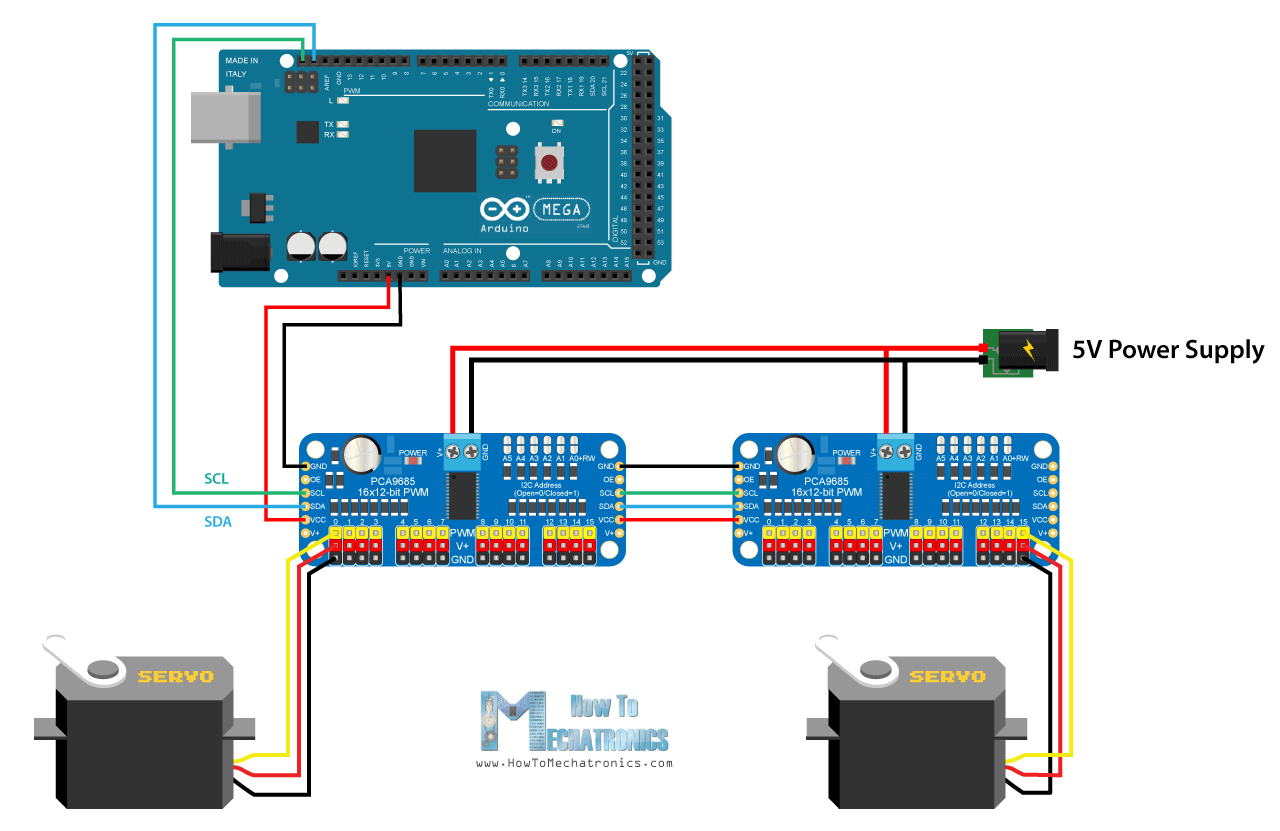
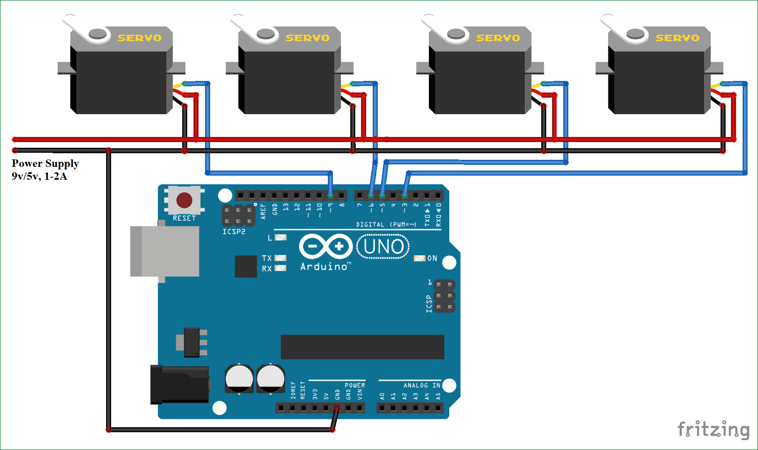
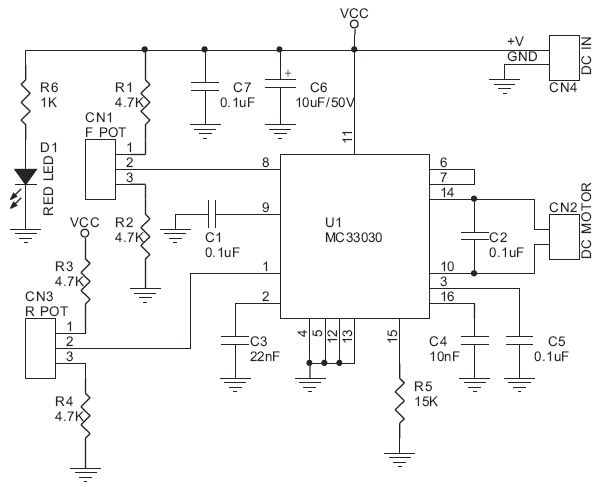
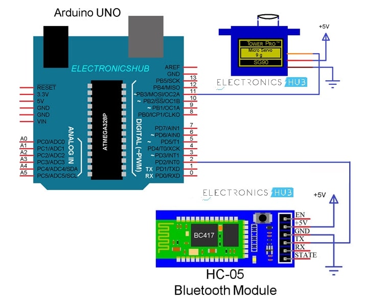
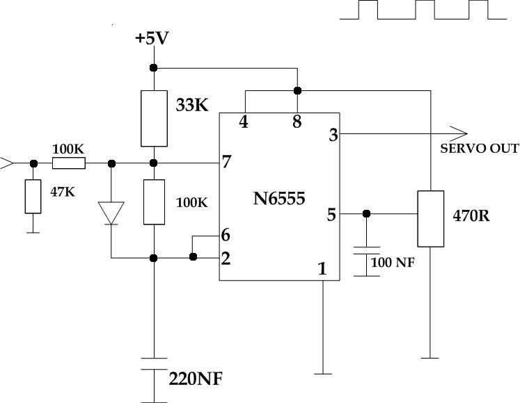
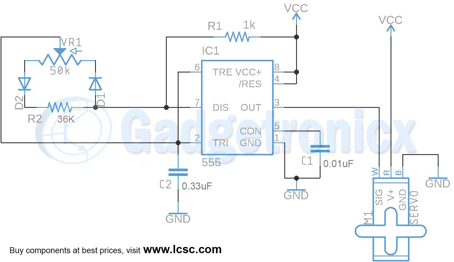
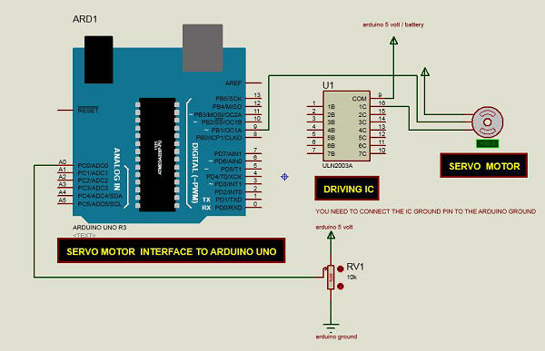
The servo motor has a female connector with three pins. It shows the components of the circuit as streamlined forms and the power and signal connections in between the devices.
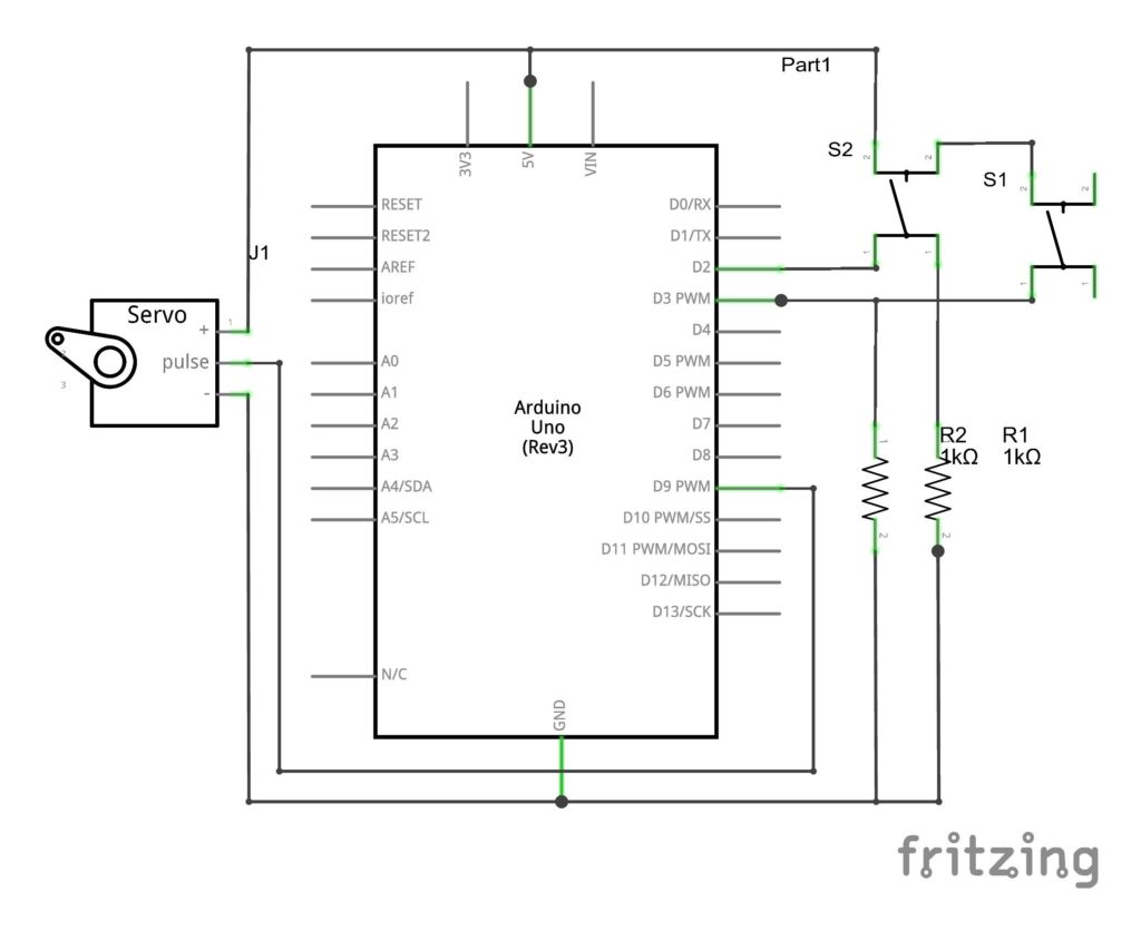
Servo Control By Push Button Switch Arduino
Servo motor connection diagram. Variety of servo motor wiring diagram. The darkest or even black one is usually the ground. A motor a feedback circuit and most important a motor driver. Since it only happens 30 times a second thats the minimum reaction time. A wiring diagram is a simplified conventional pictorial depiction of an electric circuit. As a result s ervo motors are used to control the position of objects rotate objects move legs arms or hands of robots move sensors etc.
The motor of an analog servo receives a signal from the servo amplifier inside the servo at 30 times a second. It just needs one power line one ground and one control pin. Mg90s metal gear mg995 high torque metal gear vts 08a analog servo. The following two paragraphs will help you identify the right type of servo motor for your projectsystem. Following are the steps to connect a servo motor to the arduino. Sg 90 servo motor equivalent.
You can connect small servo motors directly to an arduino to control the shaft position very precisely. This pulsing signal tells the servo motor when to start rotating and which way to rotate. Because servo motors use feedback to determine the position of the shaft you can control that position very precisely. In the most generic sense a servomechanism servo for short is a device that uses feedback to achieve the desired resultfeedback control is used in many different disciplines controlling parameters such as speed position and temperature. There are lots of servo motors available in the market and each one has its own speciality and applications. A servo motor has everything built in.
Selecting your servo motor.


