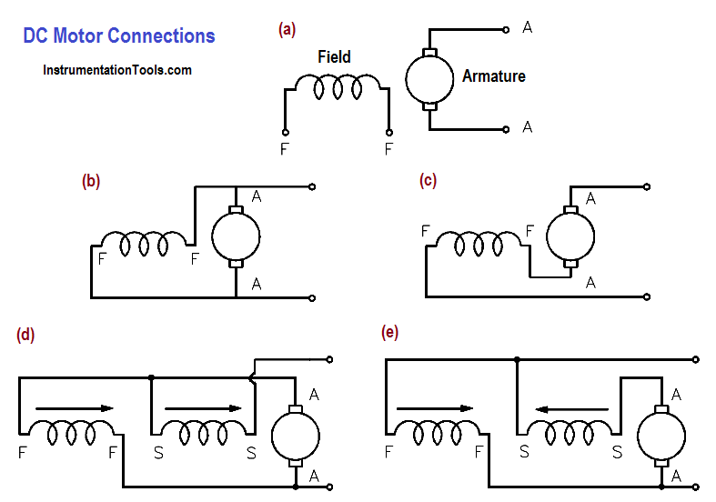
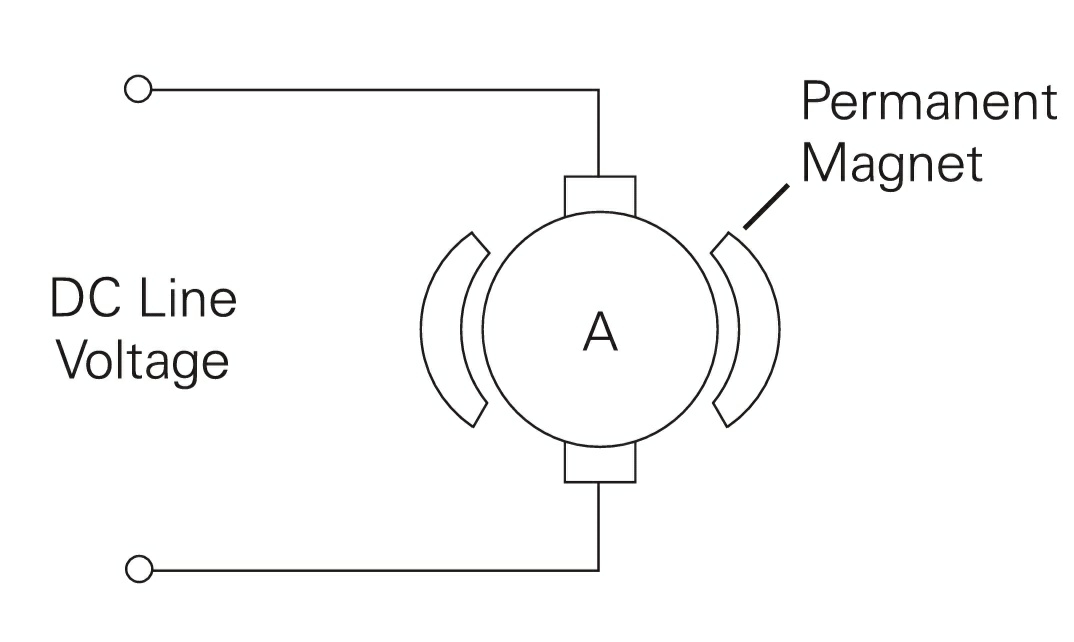
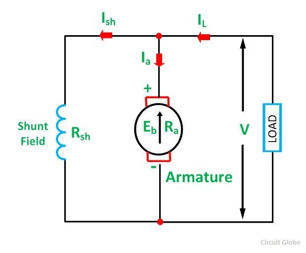
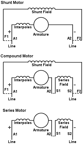
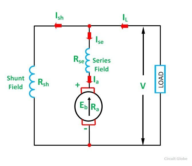
Motor connections your motor will be internally connected according to one of the diagrams shown below. The connection diagram of the dynamic braking of a dc shunt motor is shown below.
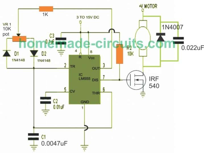
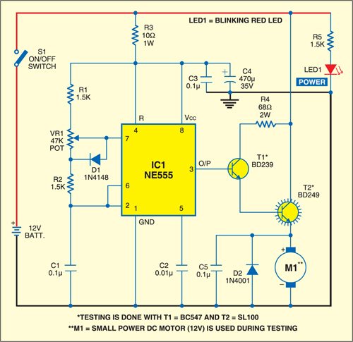
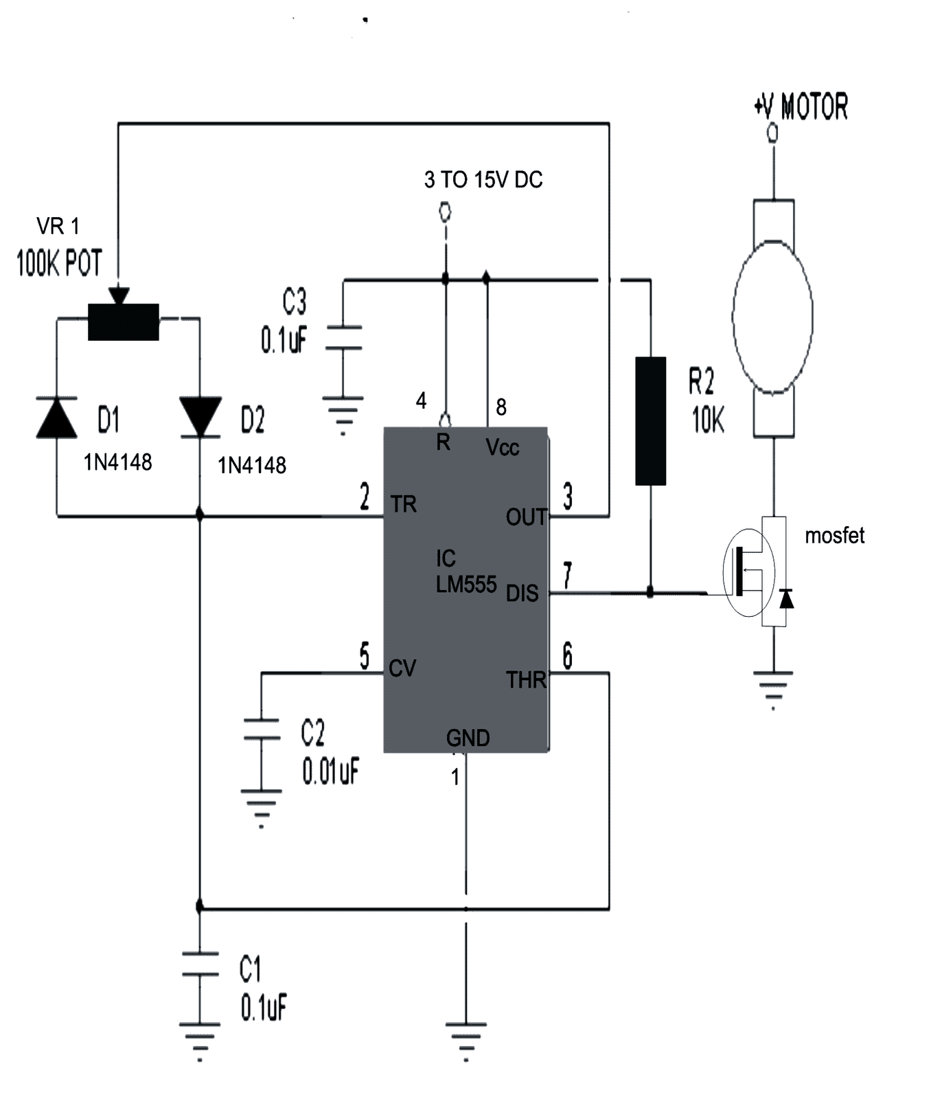
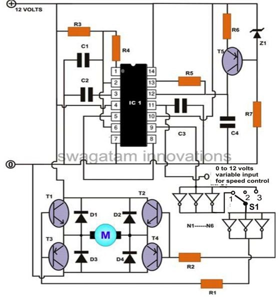
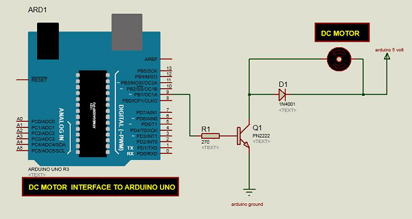
3 Simple Dc Motor Speed Controller Circuits Explained
Connection diagram of dc motor. Use figure 1 if your motor has a single voltage shunt field. To verify that this is the correct wiring diagram for your bodine product please check for the connection diagram reference number in the specifications table on the applicable itemmodel page. Single voltage wye connected with partial current transformer protection lightning arrestors surge capacitors. In the following diagram the switch s is a dpdt double pole double throw. Use figure 2 if your motor has a dual voltage shunt field. Click on the image to enlarge and then save it to your computer by right clicking.
First one is separately excited dc motor and self excited dc motor. These connections are in accordance with nema mg 1 and american standards publication 06. Types of dc motor a direct current motor dc is named according to the connection of the field winding with the armaturemainly there are two types of dc motors. Motor wiring diagram dc. The self excited motors are further classified as shunt wound or shunt motor series wound or series motor and compound wound or compound motor. The circular symbol represents the armature circuit and the squares at the side of the circle represent the brush commutator system.
The direction of the arrows indicates the direction of the magnetic fields. From this diagram the braking method can be understood. A compound wound dc motor also known as a dc compound motor is a type of self excited motor and is made up of both series the field coils s1 s2 and shunt field coils f1 f2 connected to the armature winding as shown in the figure below. The illustrations below schematically show the different methods of connecting the field and armature circuits in a dc motor. Triple rate motor connection. Star delta y δ 3 phase motor starting method by automatic star delta starter with timer.
Collection of dc motor wiring diagram 4 wire. Connection diagram for 230460vac 9 wire reversible 3 phase gearmotors and motors 07410012. Dc motor wiring diagram 4 wire ac motor wiring diagram download valid wiring diagram for dc motor free download wiring diagram. Three phase motor connection stardelta without timer power control diagrams. Motor connection diagrams electric motor wire marking connections for specific leeson motor connections go to their website and input the leeson catalog in the review box you will find connection data dimensions name plate data etc. Click download pdf to view this wiring diagram.
Three phase motor connection schematic power and control wiring installation diagrams. Single three phase blower connection diagrams thermally protected. Single voltage wye connected with partial current transformer protection.


