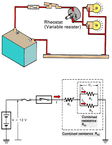
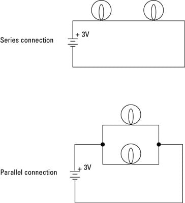
The seriesparallel configuration shown in figure 6 enables design flexibility and achieves the desired voltage and current ratings with a standard cell size. The basic idea of a series connection is that components are connected end to end in a line to form a single path through which current can flow.

Ohm S Law Electric Circuits Siyavula
Series parallel board connection diagram. Series board wiring diagram in this video im show youseries board wiring diagram. We can find out the start run common connection in electric motor or compressor. Thats the key difference between series and parallel. One may think what is the purpose of series parallel or series parallel connections of batteries or which is the right configuration to charge storage battery bank system off grid system or solar panel installationwell it depends on the system requirement ie. A 36v nominal cell multiplied by 3400mah produces 1224wh. Series and parallel circuits in our free electronics textbook.
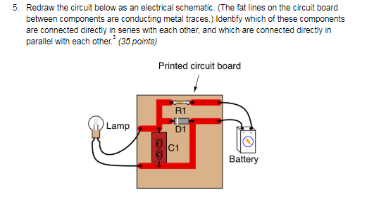
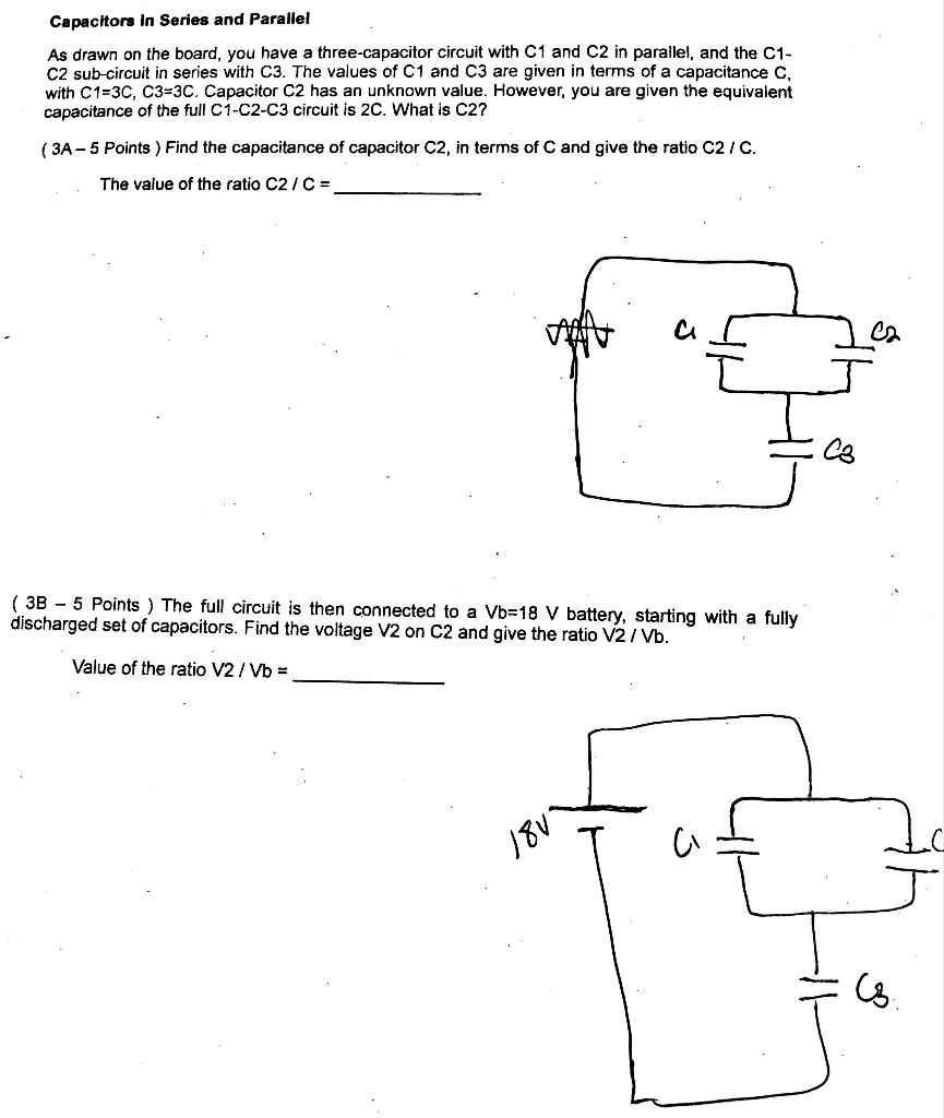
Two components are in series if they share a common node and if the same. Components connected in series are connected along a single conductive path so the same current flows through all of the components but voltage is dropped lost across each of the resistances. Series testing board but my last diagram about series board which is only for connectivity testing shortage testing or compressor terminals testing but in this post you will learn that how can you make a testing board from which you can test the low resistance electrical appliances such as electric heater iron etc. The two simplest of these are called series and parallel and occur frequently. Components of an electrical circuit or electronic circuit can be connected in series parallel or series parallel. If you like this video like comment and share with your friends.
Series parallel series parallel configuration of batteries introduction to batteries connections. We can do connection of a 3 phase motor in start delta. We can test the condactor by using this board. The recommended way to do so on a breadboard would be to arrange the resistors in approximately the same pattern as seen in the schematic for ease of relation to the schematic. The total power is the sum of voltage times current. So are points 8 7 6 and 5.
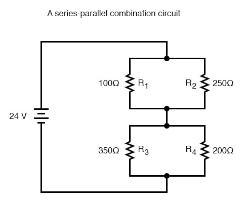
Looking at the schematic diagram we see that points 1 2 3 and 4 are all electrically common. Is video me ek aisa series board banane ka tariqa bataya gaya he jis ke zareye hum ek hi socket se series aur parallel board ka kam le sake ge basic se mokammal diagram ke sath video me is kam ko. The uses and advantage of series testing board in unlimited and we can use it for many thing. To increase the voltages by. Dont forget to subscribe. Series parallel circuit construction on a solderless breadboard suppose we wanted to construct the following series parallel combination circuit on a breadboard.
Notice that in some nodes like between r 1 and r 2 the current is the same going in as at is coming outat other nodes specifically the three way junction between r 2 r 3 and r 4 the main blue current splits into two different ones.

