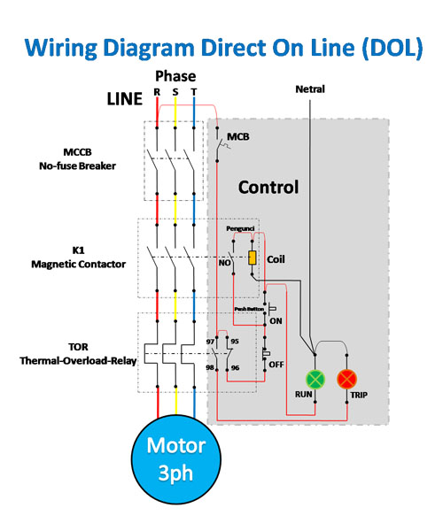
In the above one phase motor wiring i first connect a 2 pole circuit breaker and after that i connect the supply to motor starter and then i do cont actor coil wiring with normally close push button switch and normally open push button switch and in last i do connection between capacitor. If you have a 120v coil instead of running a line from coil overload l2 you must run coil overload neutral.

Siemens Furnace Wiring Diagram H1 Wiring Diagram
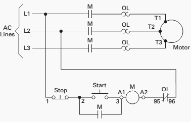
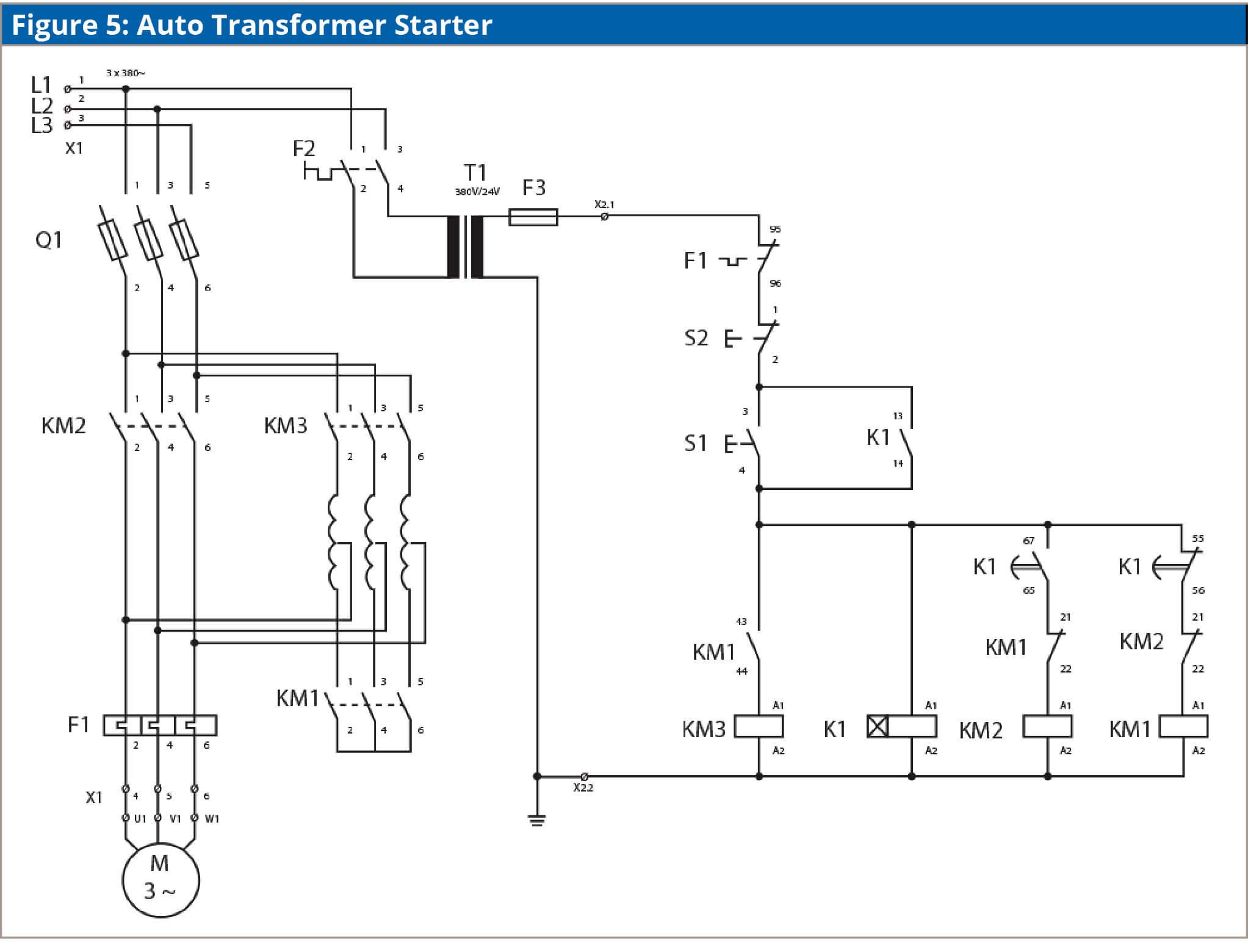
Magnetic motor starter diagram. Figure 1 typical wiring diagram. Basic wiring for motor control technical data. Square d motor starters wiring diagram sq d motor starter wiring diagram square d 3 phase motor starter wiring diagram square d 8536 motor starter wiring diagram every electric structure is composed of various distinct pieces. Magnetic starters consist of an electrical contactor and an overload which provides protection in case of a sudden loss of power. They can be used as a guide when wiring the controller. Figure 1 is a typical wiring diagram for a three phase magnetic motor starter.
In north america an induction motor will typically operate at 230v or 460v 3 phase 60 hz and has a control voltage of 115 vac or 24 vdc. The above diagram is a complete method of single phase motor wiring with circuit breaker and contactor. 3ph starter3ph motor line voltage control three phase 3ph motor starter controlling a three phase motor rev 08 aug 2006 the above wiring diagram assumes your magnetic starter has a 240v coil. Each part should be placed and linked to different parts in specific way. They show the relative location of the components. A magnetic motor starter is an electromagnetically operated device that starts and stops a connected motor load.
If not the structure wont work as it ought to be. A motor starter is a combination of devices used to start run and stop an ac induction motor based on commands from an operator or a controller.


