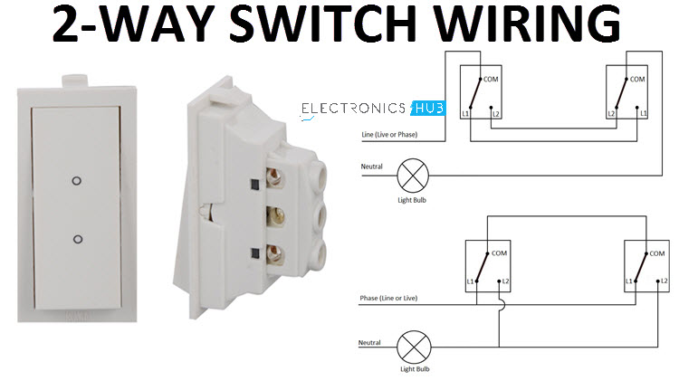
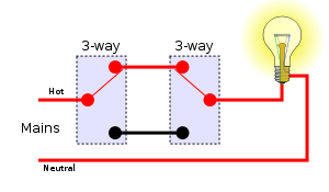
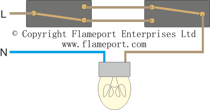
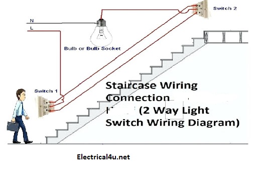
One way lighting circuit using in line switching. As you see in the schematic diagram of 2 way switch circuit below you will find that the phaselive is connected with the common of the first 2 way switch.
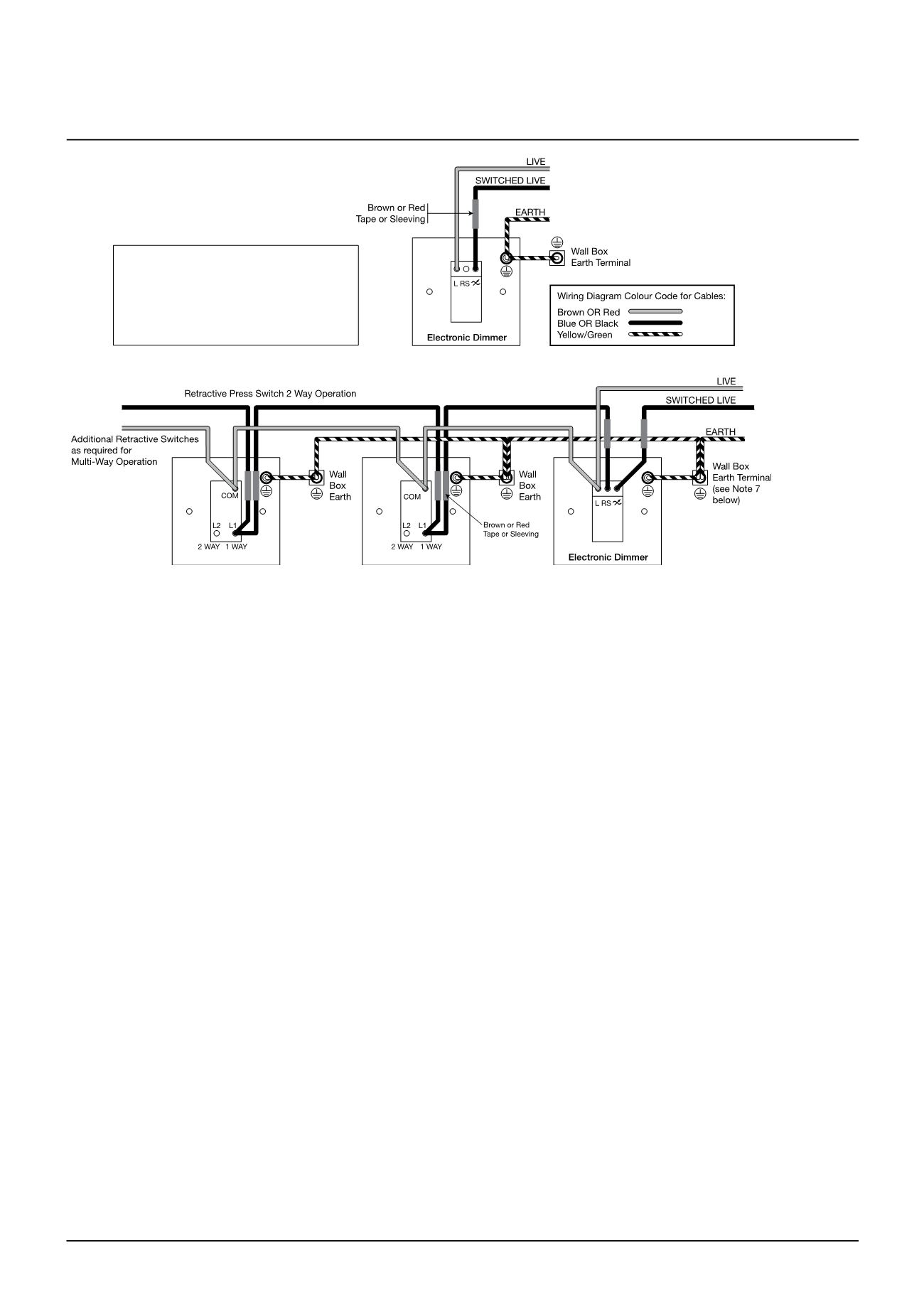
Schneider Electric Wiring Devices Lighting Control Amp Automation
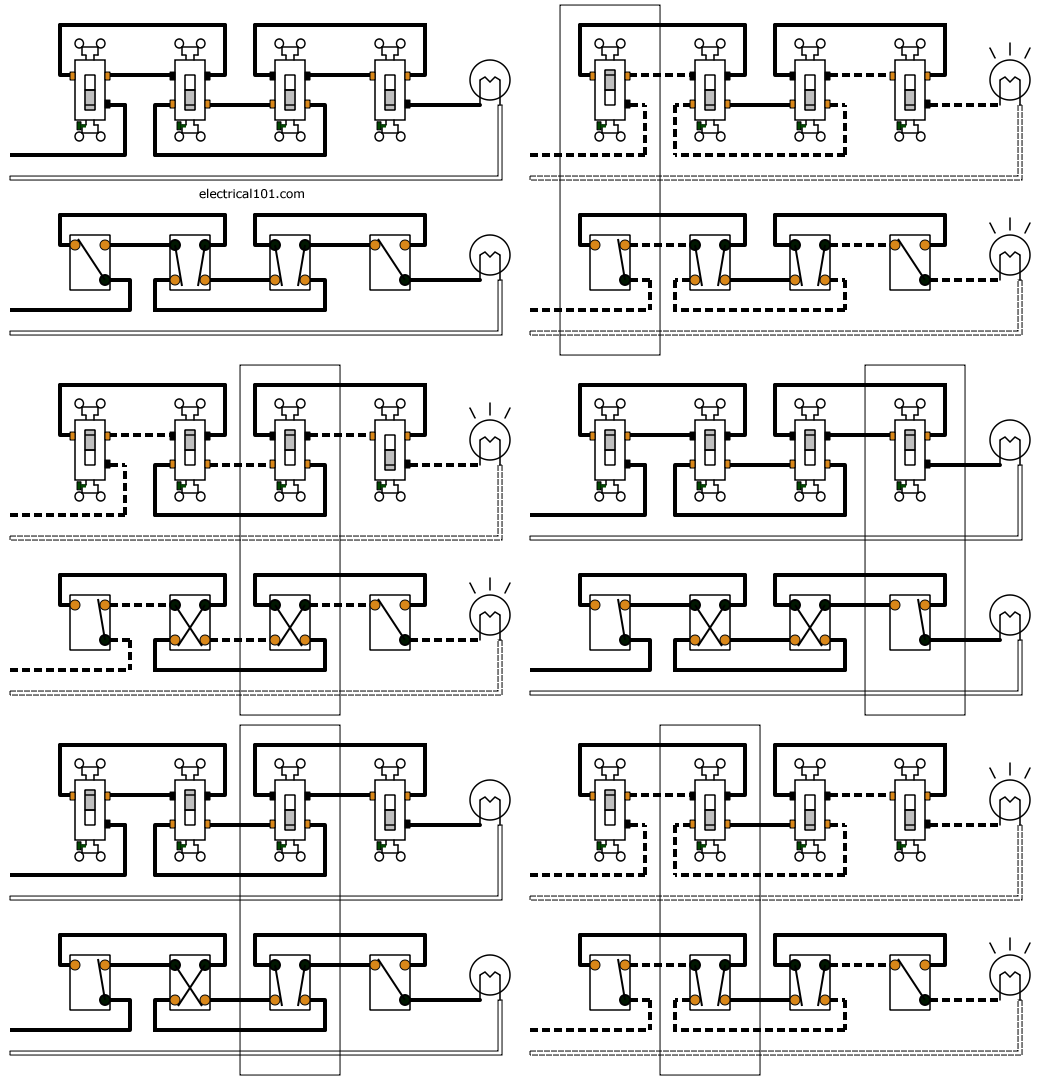
One way light switch circuit diagram. Pin1 pin2 of the first. From 7am to 6pm only the middle one bulb will glow and the first and last one will turned off. The hot and neutral terminals on each fixture are spliced with a pigtail to the circuit wires which then continue on to the next light. If you want more than three locations to control the lights you will need a 4 way switch for each of those extra locations. In tunnel wring circuit diagram we have used spdt two way switches to control the lighting points in tunnels and corridors. For a 4 way light circuit to work you need two 3 way switches and at least one 4 way switch.
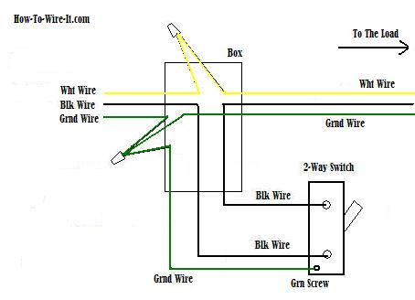
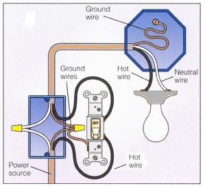
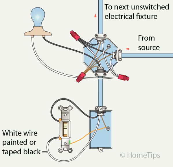
The cable going to the light switch is connected as follows fig 2. The tunnel circuit control the lamps in four ways as follow. The source is at sw1 and 2 wire cable runs from there to the fixtures. A one way light switch is quite easy to wire up. Multiple light wiring diagram. This diagram illustrates wiring for one switch to control 2 or more lights.
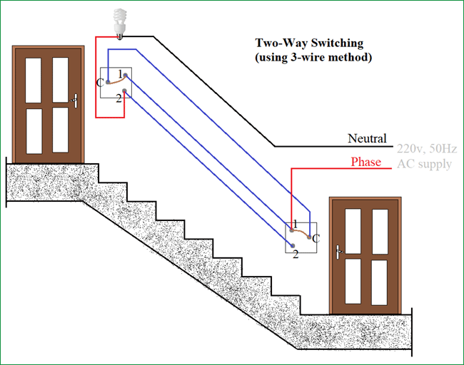
The red wire from the feed cable is connected to the top terminal the red wire going to. During normal light in the day ie. If you are going to install a new one then go for three wire control method. This is the first method to make a 2 way switching connection this is the old method. Place all the 4 way switches between the two 3 way switches. Quick 4 way light wiring.
Line diagram of a one way lighting circuit using in line method fig 1.
