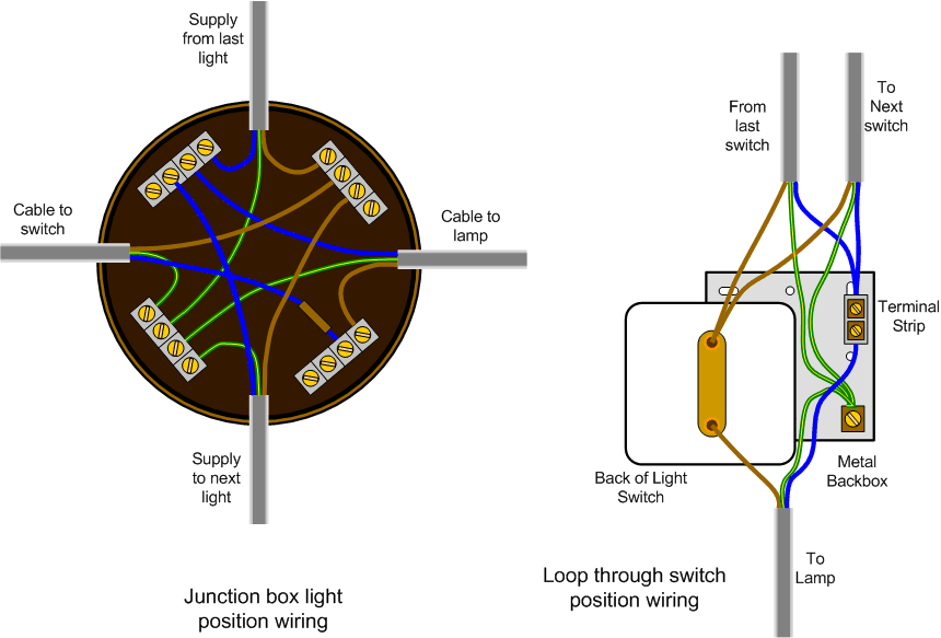
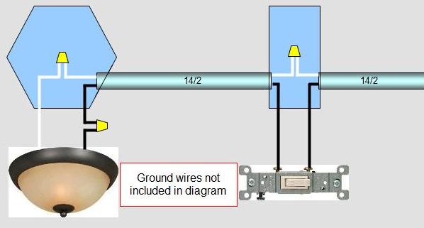
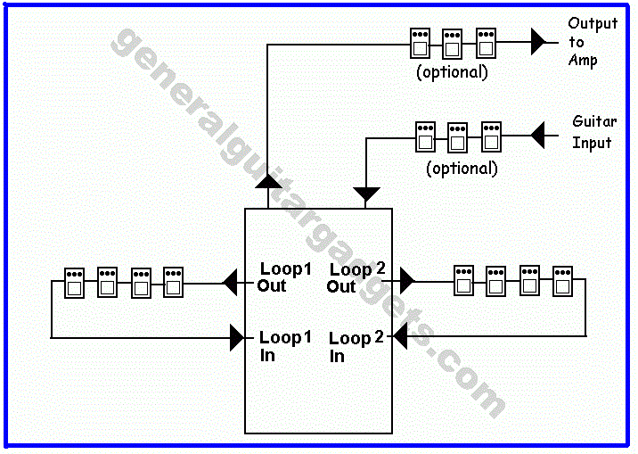
The principle is exactly the same as when looping at the ceiling rose or using a junction box. Multiple light wiring diagram.
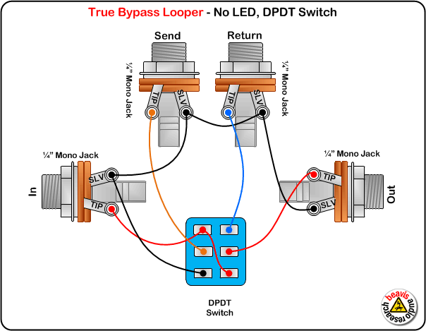
Beavis Audio Research
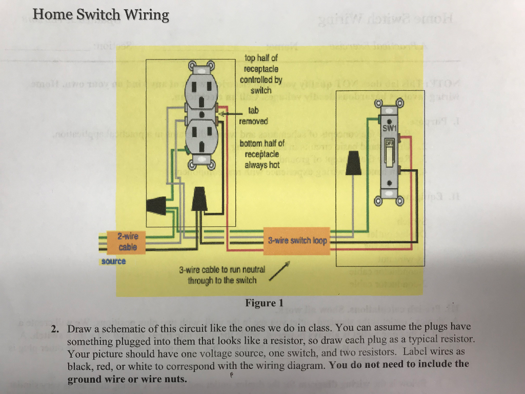
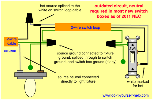
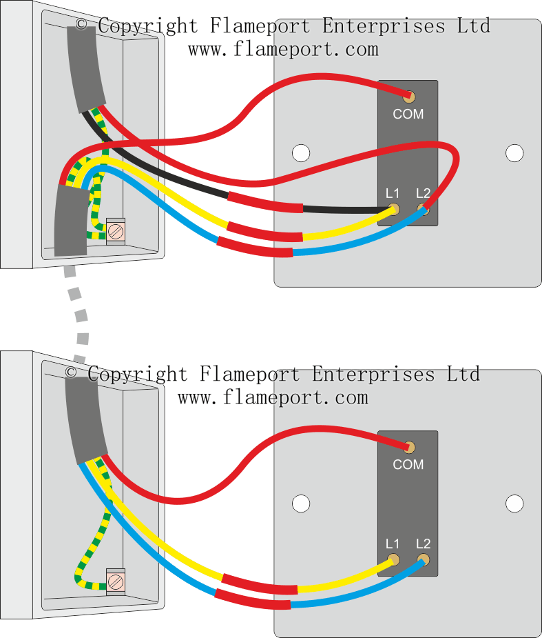
Loop at the switch wiring diagram. A switch loop occurs when both the switch at the end of a circuit or an incoming cable and a neutral become hot leads and connect to a terminal. For new wiring you would run a three wire cable and use the red and black for the loop and leave the white unused and capped in the switch box. The source is at sw1 and 2 wire cable runs from there to the fixtures. Switch loops work by stealing a hot thats in an attic or maybe in a light fixture box in the ceiling and sending that hot down to the switch on a. The hot and neutral terminals on each fixture are spliced with a pigtail to the circuit wires which then continue on to the next light. Lighting circuits loop at the switch.
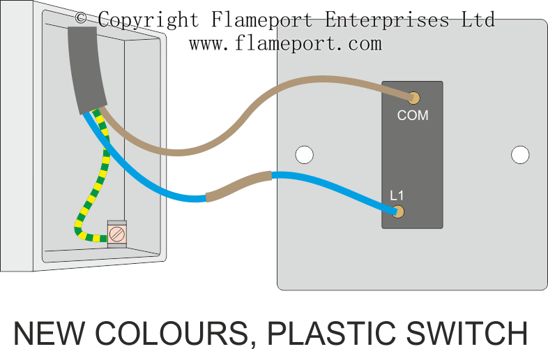
How does electrical switch wiring work. This is a loop in method which can be useful where the light fitting only has three terminals or when using downlighters. Loop at the switch. The in cable supplies power from the previous light or consumer unit. The part that confuses most people when wiring a switch loop is that youre twisting together a black and a white wire. In a switch loop this is not how its done.
They dont think about each wire as a conductor they think of them as a hot. Bib jun 1 15 at 1238 1 if you are working on an older home with unmarked switch loops when you trace them also mark the white wires that should be marked so that they are marked for the next. In a switch loop the hot and neutral wires arrive at the light fixture before reaching the switch. This diagram illustrates wiring for one switch to control 2 or more lights.

