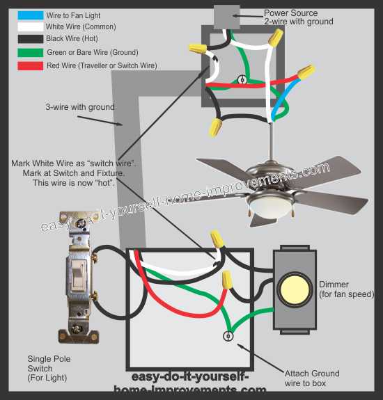
Assortment of hunter ceiling fan wiring diagram with remote control. The red wire is for the fan light.

How To Bypass A Ceiling Fan Remote Control Juggling Dad S Balls
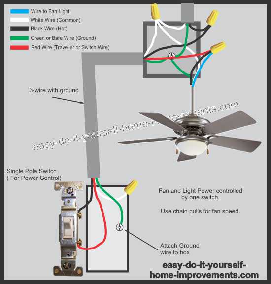
Intertek fan and light control wiring diagram. From the switches 3 wire cable runs to the ceiling outlet box. Intertek fan remote wiring diagram by saum hadi posted on january 9 2020 wiring diagrams for a ceiling fan and light kit do it intertek ceiling fan fakesartoria fan wire diagram wiring library 12 volt led light strips powering and wiring ledsupply electrical controls. R e m ov wa lp t d is cn r hg f b x. Intertek ceiling fan wiring. The white neutral wire is for the incoming neutral wire. The black wire is for the fan motor.
It reveals the components of the circuit as simplified shapes and the power and signal links between the devices. More about wiring ceiling fans and remote controls. Intertek ceiling fan wiring diagram. The source is at the switches and the input of each is spliced to the black source wire with a wire nut. The black wire is for the incoming power line. The white common wire is the common for the white wire of the fan and the light.
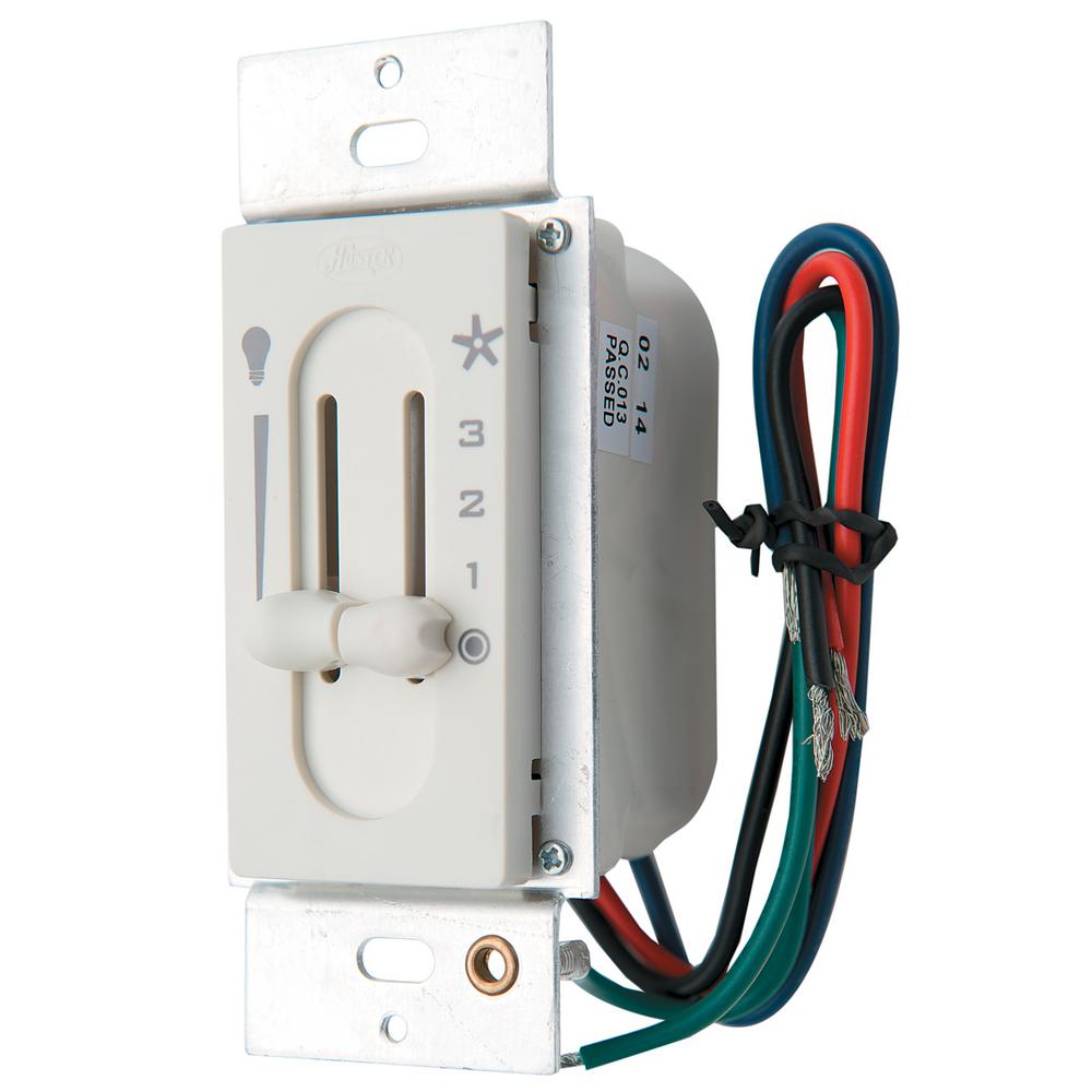
Manually set fan speed control to high via pull chain and set light to on via pull chain. How to install. Installing wall control transmitter. A wiring diagram is a simplified traditional pictorial depiction of an electrical circuit. Whats people lookup in this blog. Fan speed and light control will not be activated by remote if pull chains for fan and light a r eno tsh hig a d on p i c v ly.
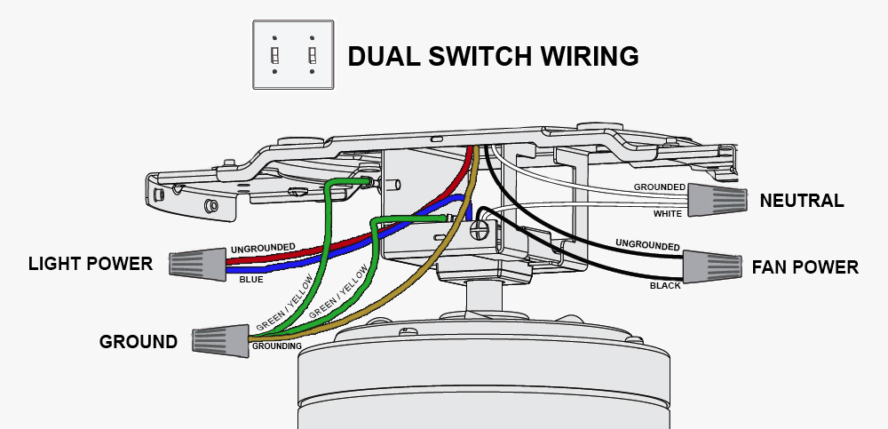
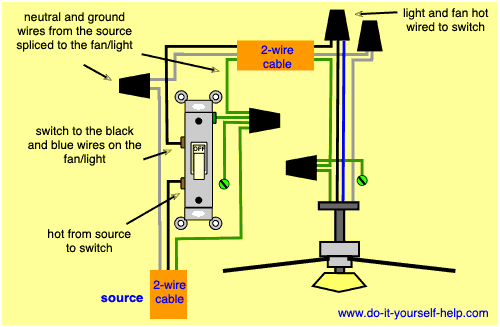
Ceiling fan wiring diagram install and wire a ceiling fan ceiling fan wiring diagram how to install a ceiling fan with remote control you. This wiring diagram illustrates the connections for a ceiling fan and light with two switches a speed controller for the fan and a dimmer for the lights.

