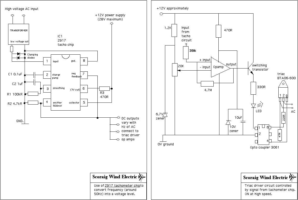
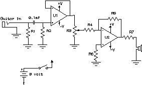
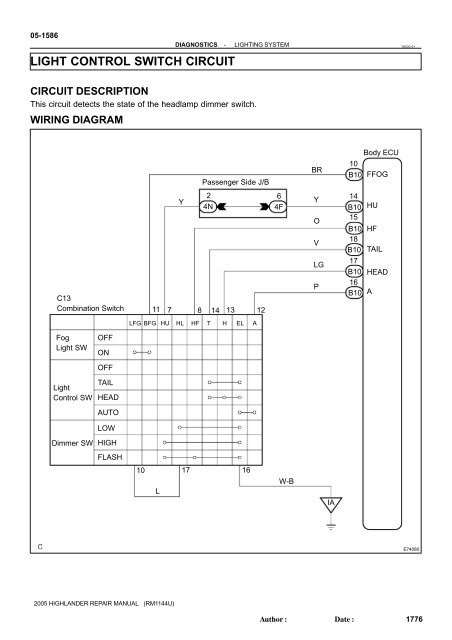
After seeing a few circuit diagrams youll quickly learn how to distinguish the different symbols. Knowing how to read circuits is a very useful skill that will help you out all the time.
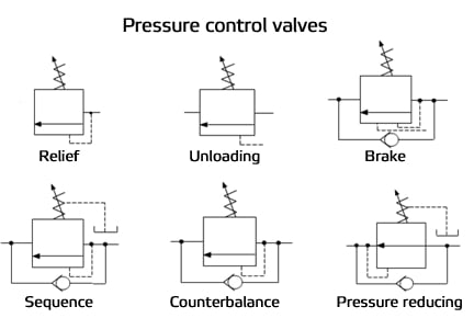
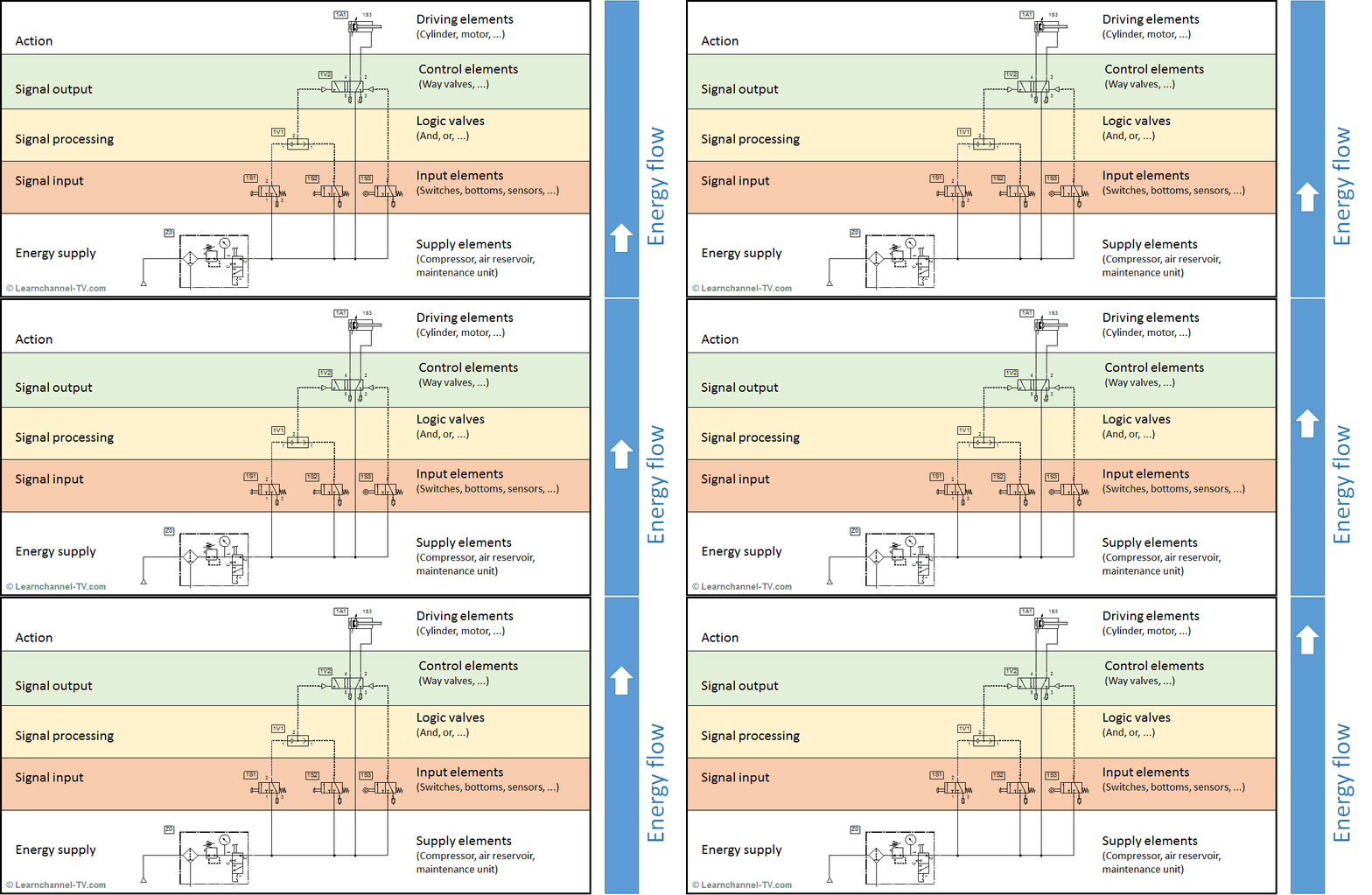
Reading Fluids Circuit Diagrams Hydraulic Amp Pneumatic Symbols
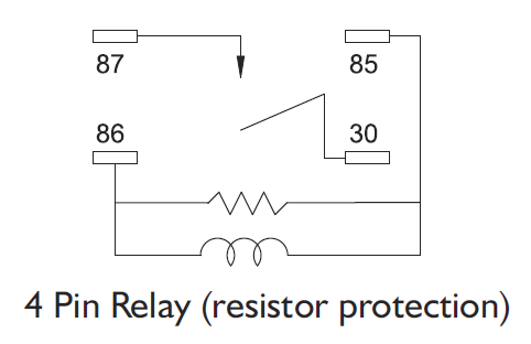
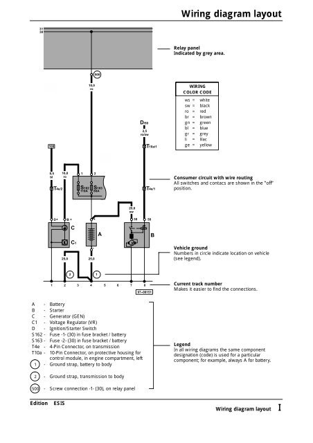
How to read control circuit diagram. The first circuit to be discussed is a basic control circuit used throughout industry. This tutorial should turn you into a fully literate schematic reader. See more ideas about circuit diagram circuit electronics circuit. We begin with a basics fuel pump relay diagram. Especially if you start messing around with building little electronics projects. Each electronic component has a symbol.
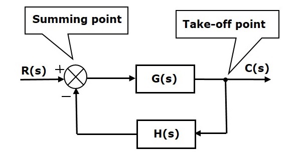
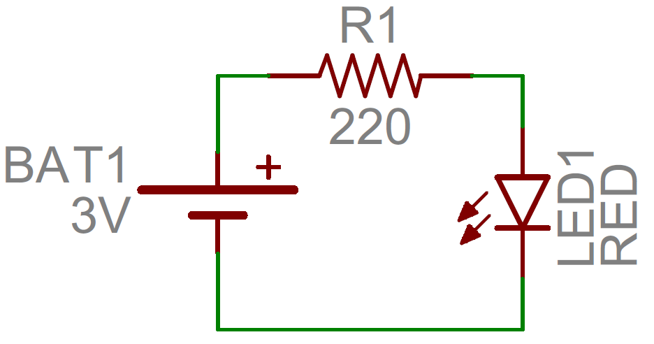
It is not difficult to learn the basic symbols. It is also necessary to understand how the components are connected together in. This instructable will show you exactly how to read all those confusing circuit diagrams and then how to assemble the circuits on a breadboard. In order to learn how to read a circuit diagram it is necessary to learn what the schematic symbol of a component looks like. Circuit or schematic diagrams consist of symbols representing physical components and lines representing wires or electrical conductors. Both line and wiring diagrams are a language of pictures.
Well also go over a. For all the electronics hobbyist wannabes this is a must read instructable. We show our ac power source on the left with l1 and n coming out of it our switch to the top and our light to the left. Figure 914 shows a start stop push button circuit. Understanding how to read and follow schematics is an important skill for any electronics engineer. Schematic diagrams do not always show both control and motor connections.
Well go over all of the fundamental schematic symbols. Once you do you are able to read diagrams quickly and can often understand a circuit at a glance. To begin understanding how to read and understand electrical circuit diagrams take our basic circuit and draw it out as it would physically be wired. Jun 30 2020 explore juni joness board circuit diagram on pinterest. Many schematic diagrams show only the control circuit. Then well talk about how those symbols are connected on schematics to create a model of a circuit.
Volts amps watts fuse sizing wire gauge acdc solar power and more. A circuit diagram or a schematic diagram is a technical drawing of how to connect electronic components to get a certain function. Standardized symbols make diagrams easier to read. This schematic shows both the control circuit and the motor circuit.
