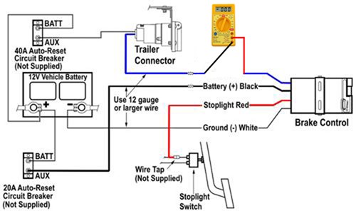
Controller called the predator dx2. This controller features an accelerometer design which senses the deceleration of the towing vehicle and sends a proportional voltage to the electric trailer brakes.

Journey Trailer Brake Controller Wiring Diagram Wiring Diagram
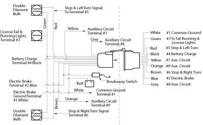
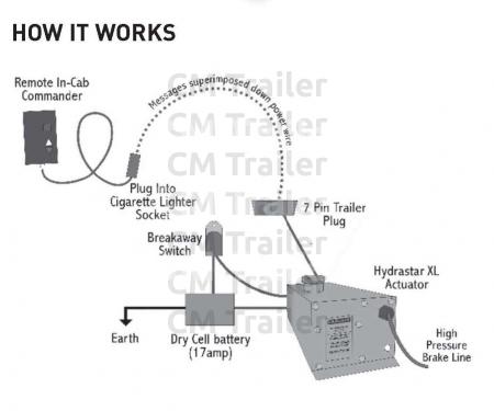
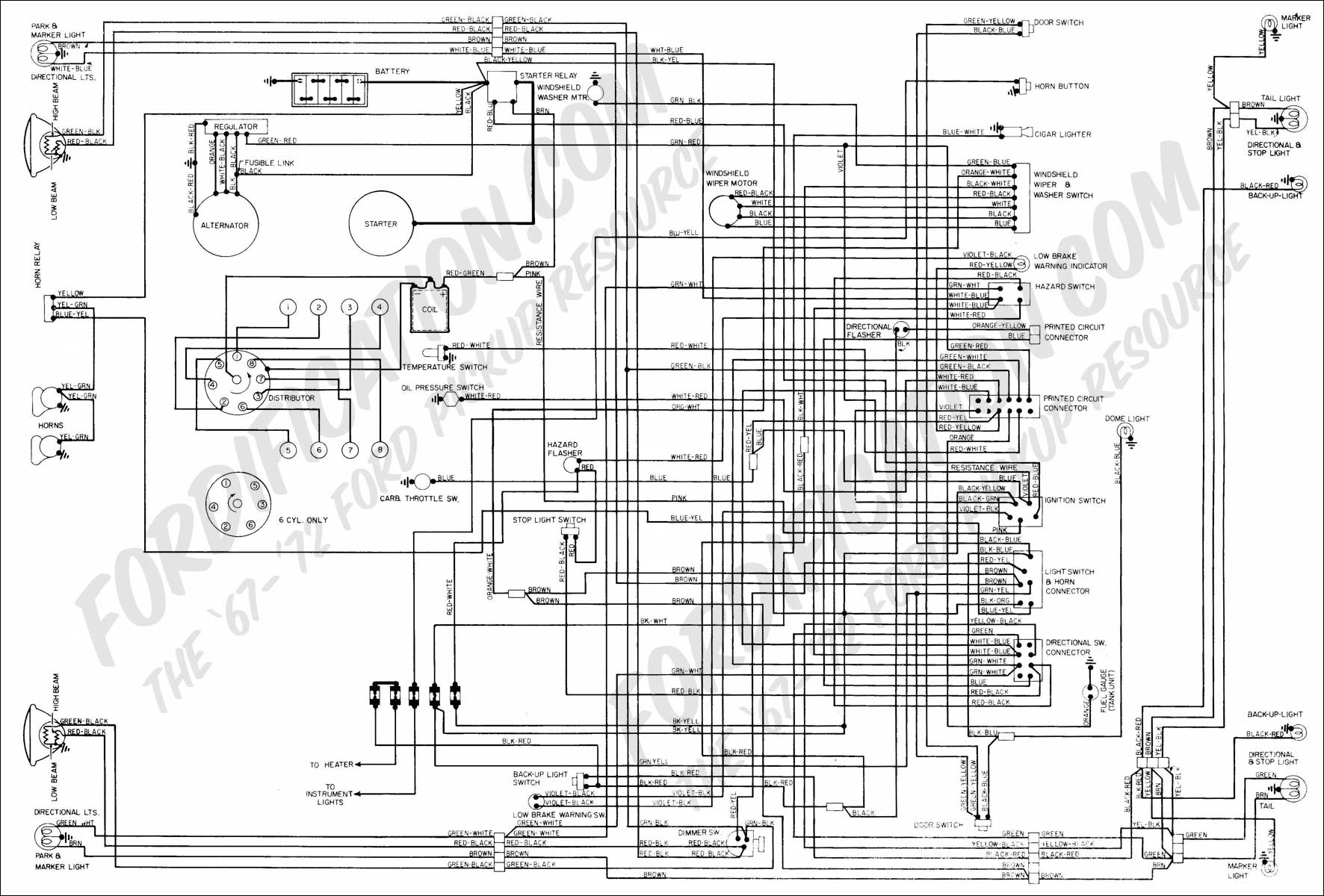
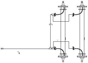
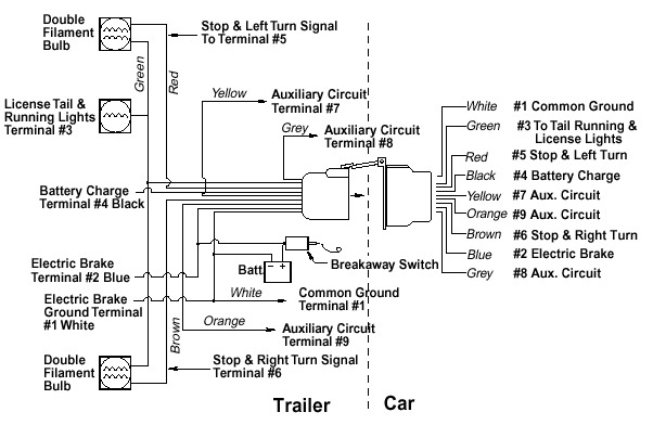
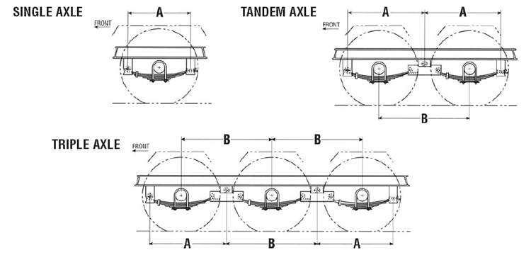
Dexter trailer brake wiring diagram. How to wire the dexter electric over hydraulic trailer brake actuator question. Typical electric hydraulic brake system diagram breakaway switch eh actuator trailer plug electric wires hydraulic lines to trailer brakes dexter hydraulic drum brake or disc brake electric brake controller breakaway battery dexter axle eh units model eh 1000 pn k71 650 00 for drum brakes only model eh 1600 pn k71 651 00 for disc. Dexter trailer brakes wiring diagram dexter axle brake actuator wiring diagram dexter axle brake wiring diagram dexter hydraulic trailer brakes wiring diagram people today understand that trailer is a vehicle comprised of rather complicated mechanisms. Dexter offers a state of the art inertial. Trailer wiring 7 electric brake line diagram 8 9 wiring recommendations 10 parking brake option 11 correct use of your electric brakes 11 to synchronise tow vehicle trailer braking 13 controllers 14 general maintenance brake adjustment 15 brake cleaning and inspection 16 brake lubrication 16 magnets 17 shoes and linings 17. Electric brake controllers provide power to the magnets to actuate the trailer brakes.
This automobile is designed not just to travel 1 location to another but also to carry heavy loads. Is the 12 volt 30 amp power supply black cable and earth white cable wired through the 7 pin plug on the tow vehicle or a stand alone power circuit.

