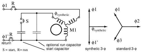
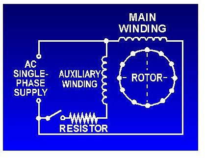
Split phase motor wiring diagram. Or single phase motor with centrifugal switch wiring diagram.

4 Pole Electric Motor Wiring Diagram H1 Wiring Diagram
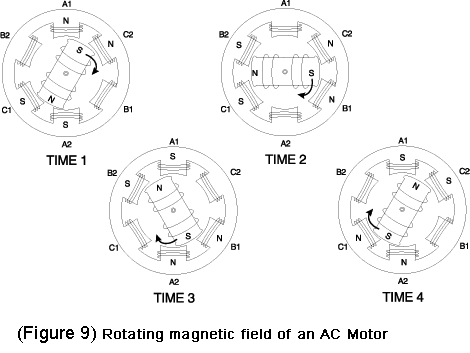
3 phase 4 pole induction motor wiring diagram. The split phase motor can be found in applications requiring 120 hp up to 13 hp meaning it can turn anything from blades on a ceiling fan washing machines tubs blower motors for oil furnaces and small pumps. Episode 4 single phase induction and shaded pole motors. In this video i showed motor rewinding 36 slots 3 phase 6 pole with diagram. And how to connect the both winding with one another. In the single phase 36 slots winding diagram. Here i described and calculate all data.
This video is perfect. Connecting a 3 phase motor with 1 phase power with diagram duration. The basic diagram view a shows a circle with two leads labeled t1 and t2. Capacitor motor single phase wiring diagrams always use wiring diagram supplied on motor nameplate. W2 cj2 ui vi wi w2 cj2 ui vi wi a cow voltage y high voltage z t4 til t12 10 til t4 t5 ali l2 t12 ti blu t2 wht t3org t4 yel t5 blk t6 gry t7 pnk. This post is about the single phase 4 pole induction motor winding diagram with centrifugal switch.
Just as in the three phase motor diagram the motor shows the power supply lines as being identified with the t. If you new and want to learn induction motor rewinding. To take household wiring as an. The shortest possible answer to the question of why tesla motors uses a 3 phase 4 pole ac induction motor to power all its cars is of course because. A shaded pole electric motor is a single phase induction motor provided with an auxiliary short circuited winding or windings displaced in magnetic position from the main winding. And wiring them without the wire labels.
Diagram ic1 3ø wiring diagrams 1ø wiring diagrams diagram er9 m 3 1 5 9 3 7 11 low speed high speed u1 v1 w1 w2 u2 v2 tk tk thermal overloads two speed stardelta motor switch m 3 0 10v 20v 415v ac 4 20ma outp uts diagram ic2 m 1 240v ac 0 10v outp ut diagram ic3 m 1 0 10v 4 20ma 240v ac outp uts these diagrams are current at the time of. In many cases the single phase motors on board aplease check my motor wiring diagram mig welding. The main winding and starting or auxiliary winding connection shown. There are a number of different construction methods used but the basic principle is the same. For most shore facility applications this is the case.

