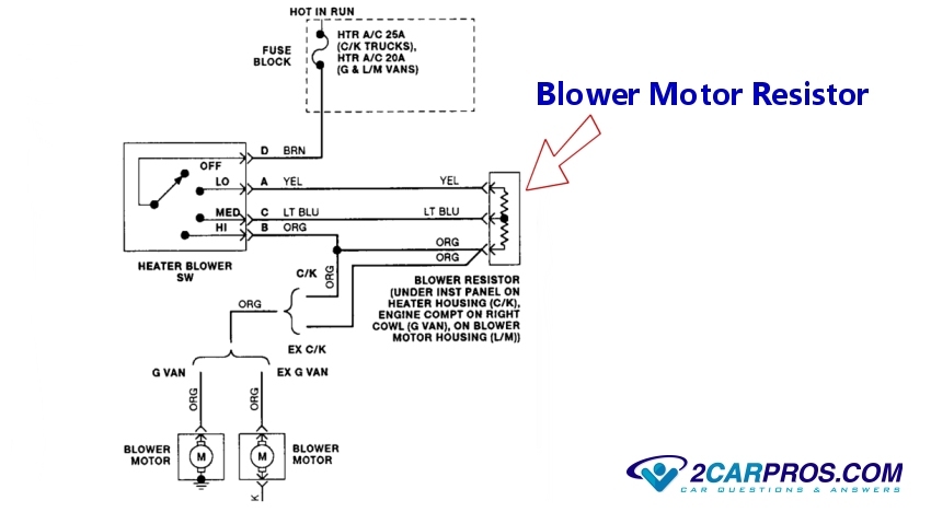
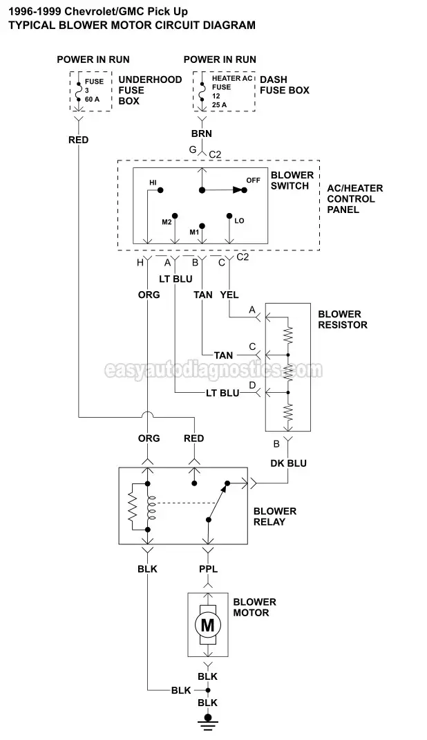
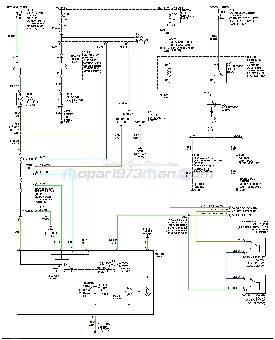
Blower motor resistor replacement how to repair heater fan speed control. This typical circuit diagram of the blower motor and blower resistor circuit applies to the 1996 1997 1998 1999 chevroletgmc 1500 2500 and 3500 pick ups.

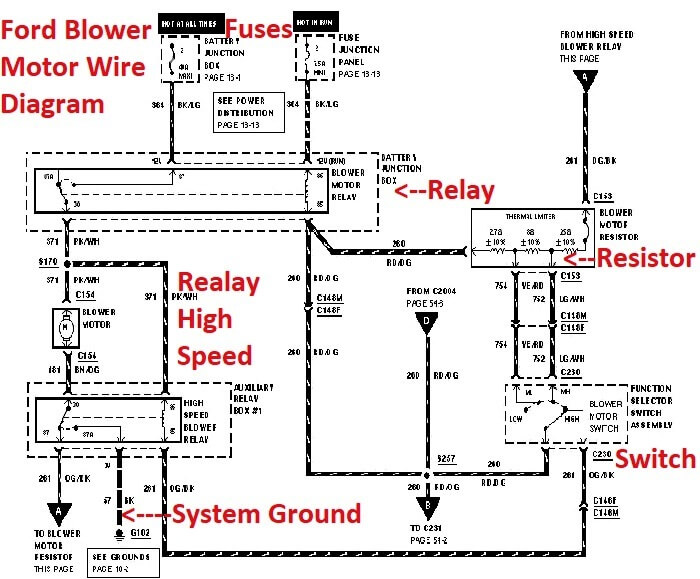
F350 Blower Motor Wiring Diagram C3 Wiring Diagram
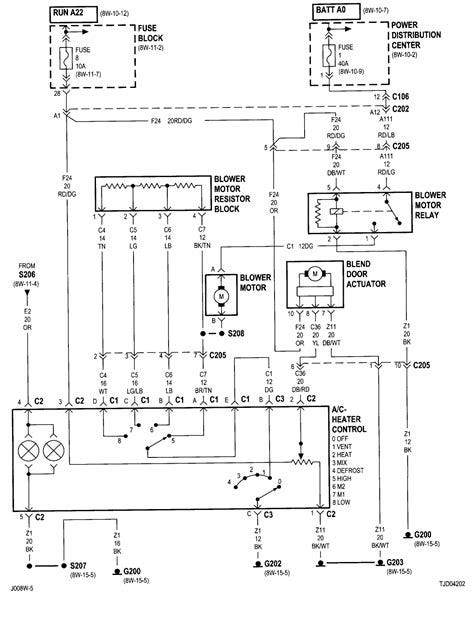
Heater blower motor wiring diagram. It shows the parts of the circuit as streamlined forms and the power and signal links in between the tools. See the wiring diagram below for that setup. The blower motor should have two wires going to it a dark green and red which. Or carmakers can opt for a motor resistor and a high speed relay. It shows the parts of the circuit as streamlined shapes and the power as well as signal connections in between the devices. Assortment of furnace blower motor wiring diagram.
A wiring diagram is a streamlined conventional photographic representation of an electrical circuit. Variable speed blower motors dont use a blower motor resistor. Gray wire in location a of the c1 connector its in the center of the diagram. Assortment of heater blower motor wiring diagram. Instead they use a blower motor speed control or a power transistor. There is a relay in the under hood fuse box blower motor relay when switched to high it energizes the relay allowing power from the hvac fuse 30 amp to flow direct to the blower motor.
Blower motor wiring diagram for variable speed systems. I have a 2000 jeep wrangler 6. A wiring diagram is a simplified traditional pictorial representation of an electrical circuit. From pin 30 to pin 87 if you look on the side of the relay there is a diagram for all other speeds the current flows from the switch through the resistor through pin 87a to pin 30 on to the blower motor. 1984 chevy gmc vacuum diagram routing solved.

