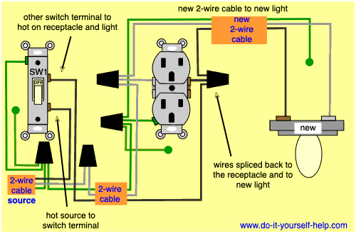
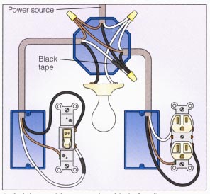
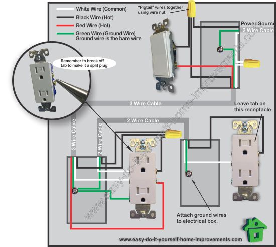
This wiring diagram illustrates adding wiring for a light switch to control an existing wall outlet. Wrapping the wire clockwise when wiring a light switch ensures that the loop on the end of the wire will tend to close when the screw is tightened.
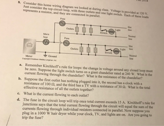
Solved Lan 2018 8 Consider This Home Wiring Diagram We L
Wiring diagram for a light switch and outlet. My light switch wiring diagrams may be helpful to you. Is it possible to wire a switch for a light and at the same time connect an outlet to the switch that will not power off and on with the switch. How to wire an electrical outlet wiring diagram wiring an electrical outlet receptacle is quite an easy job. Wiring a gfci combo switchoutlet with protected light outlet receptacle. This diagram illustrates wiring for one switch to control 2 or more lights. If you put the loop over the screw in the counterclockwise direction tightening the screw will force the loop open and could create a loose connection.
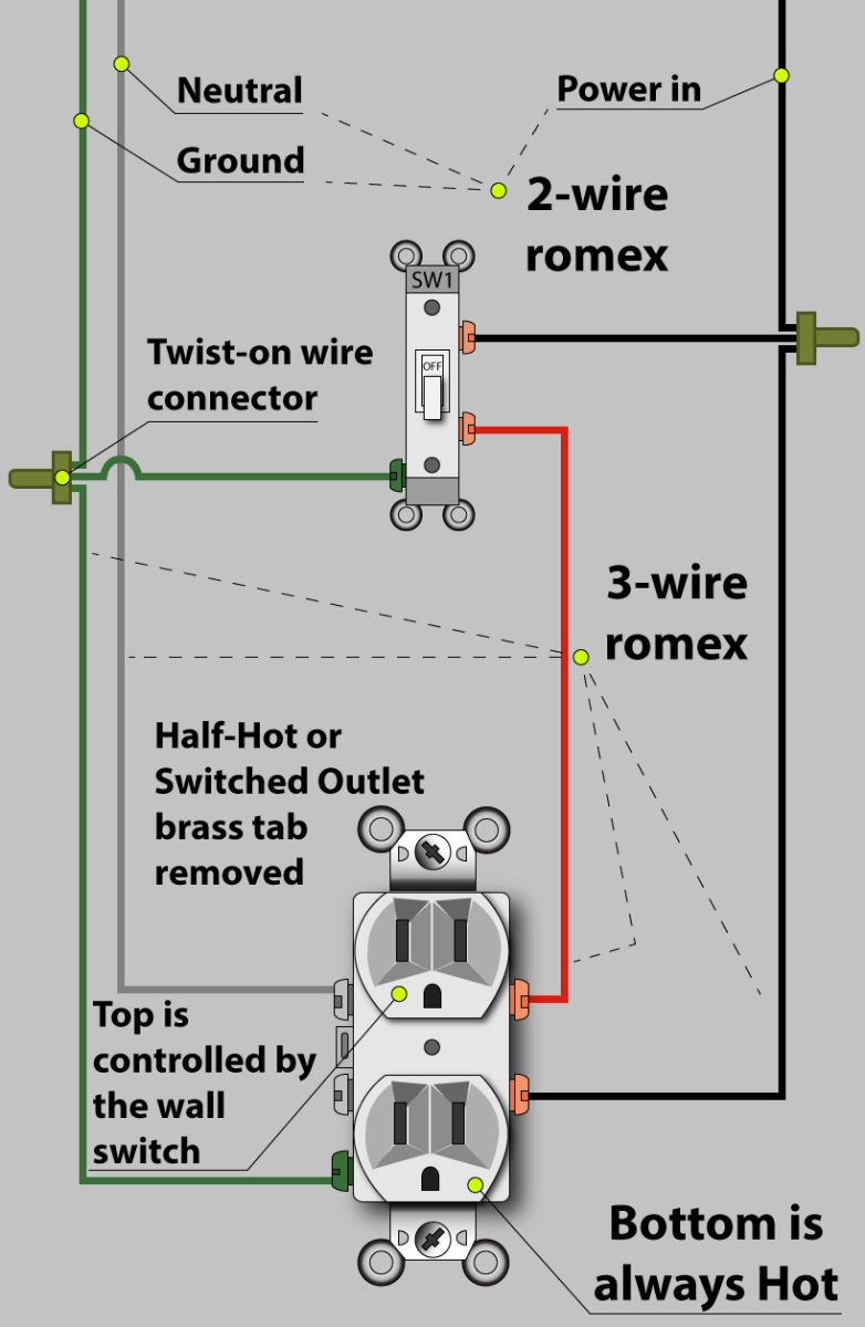
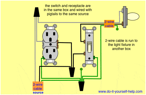
Also shown is the half of the receptacle that is live at all times and the tab that must be cut in order to split the receptacles. The light onoff operation can be controlled through the gfci switch while the ordinary outlet is directly connected to the gfci load terminals. The source is at the outlet and a switch loop is added to a new switch. Wiring an outlet to a switch loop. Light switch to outlet wiring diagram light switch outlet combo wiring diagram light switch to outlet wiring diagram every electric arrangement is composed of various unique parts. The source is at sw1 and 2 wire cable runs from there to the fixtures.
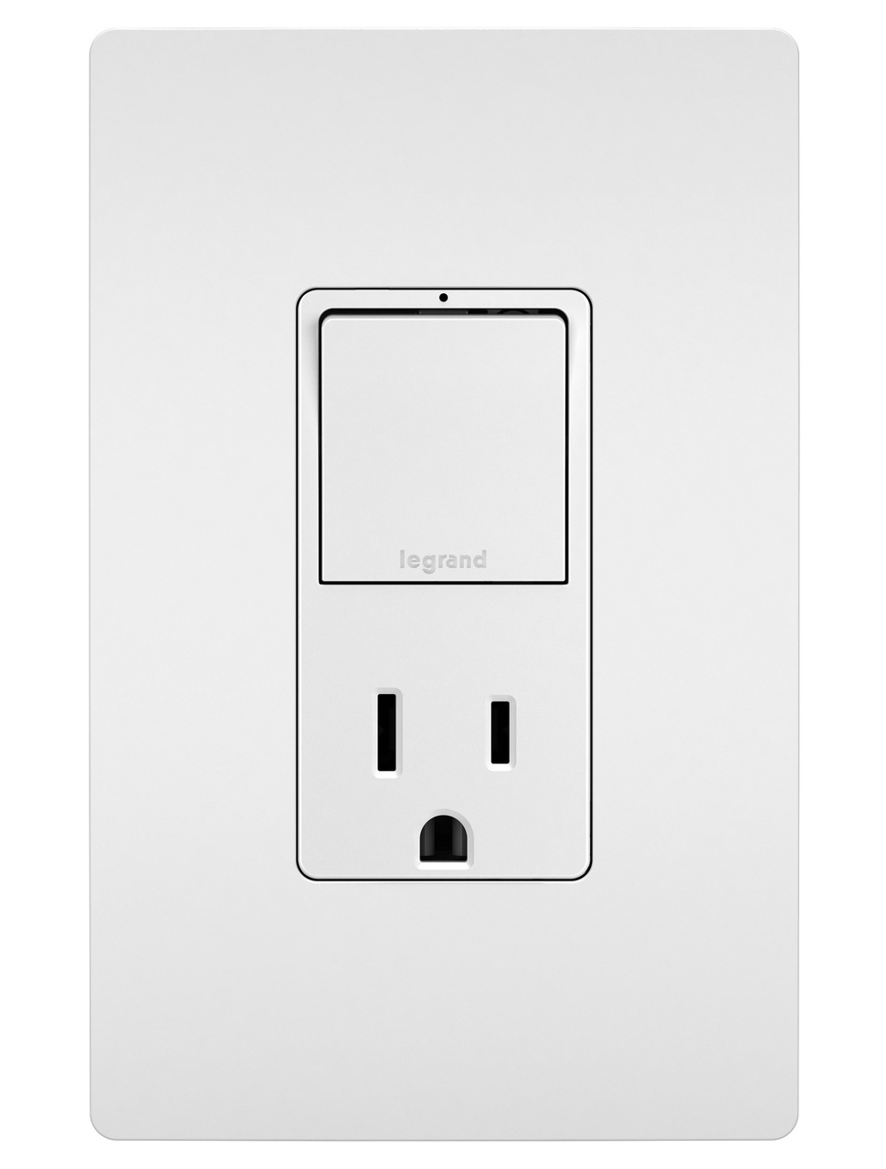
Wiring a combo switch outlet. Wiring a switch with an outlet. Mike a handyman from fort dodge iowa. Each part should be set and linked to other parts in particular way. This electrical wiring question came from. Electrical wiring for a switch outlet combination.
In this special case wiring diagram both light and ordinary outlet is connected to the load terminals of gfci. 2 way light switch wiring diagram. The hot source wire is removed from the receptacle and spliced to the red wire running to the switch. You can change this duplex receptacle to a switchreceptacle combination so that you still have power in the outlet but can use the switch to control your new overhead task light. How to install electrical outlet and switch combo wiring in most cases the primary power source is shared between the switch and the outlet either with a wire jumper or the bridge or tab that is located on the side of the combo switch and outlet. Multiple light wiring diagram.
Steps to take when wiring the electrical outletreceptacle. Fishing in a wire from the receptacle to the light fixture is fairly easy so this is how you would wire the switchreceptacle combo device in this situation. Switched split outlet wiring diagram for controlling the half of two duplex electrical receptacles by a wall switch without a neutral conductor. If you are fixing more than one outlet the wiring can be done in parallel or in series. The hot and neutral terminals on each fixture are spliced with a pigtail to the circuit wires which then continue on to the next light. Otherwise the structure will not function as it should be.


