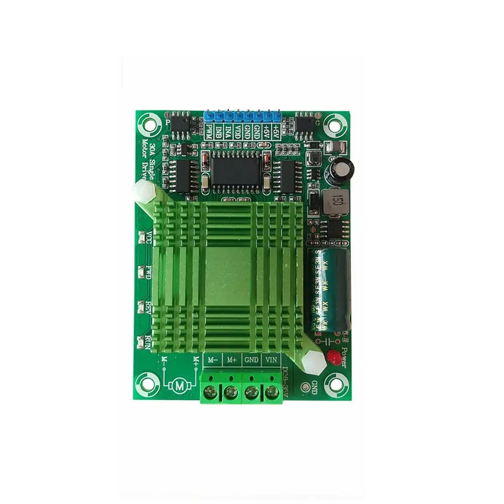
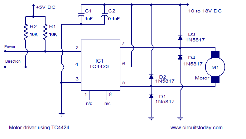
The h bridge described in this write up is capable of currents up to about 40a at 24v but requires the assembly of a pcb. The lv8762t is an 1ch h bridge driver that can control four operation modes forward reverse brake and standby of a motor.

Current Sensing In An H Bridge Eeweb Community
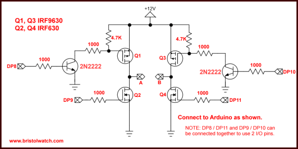
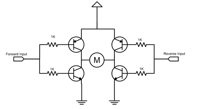
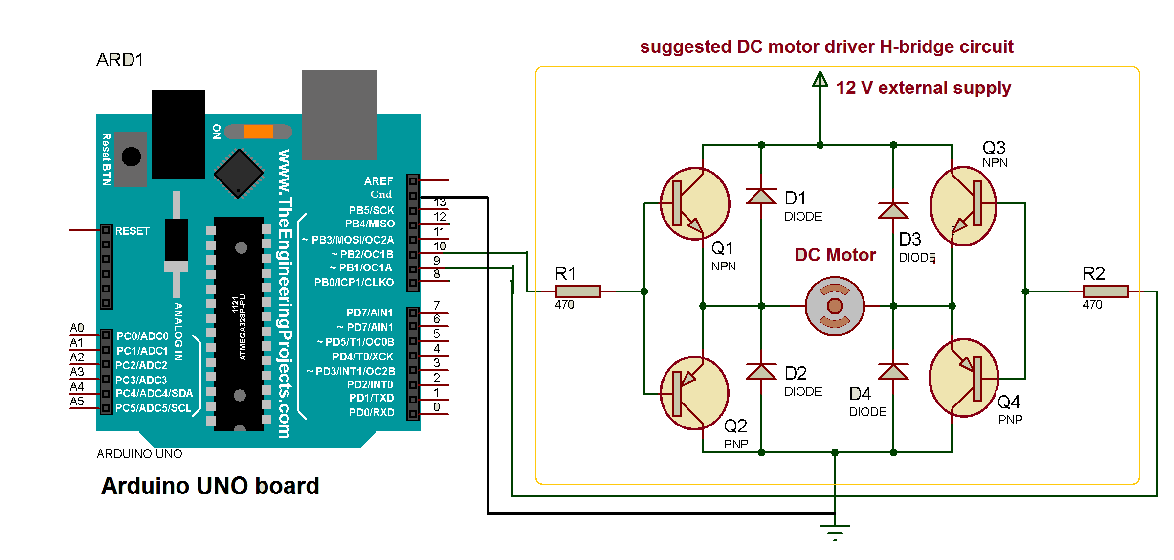
H bridge circuit diagram with forward reverse. When you can control two motors to go either forward or backward you can build yourself a robot. You normally use it with a microcontroller such as an arduino to control motors. Features forwardreverse h bridge motor driver. To apply a forward voltage across the motor mosfets 14on. An h bridge is a simple circuit that lets you control a dc motor to go backward or forward. Most dc to ac converters power inverters most acac converters the dc to dc pushpull converter most motor controllers and many other kinds of power electronics use h bridges.
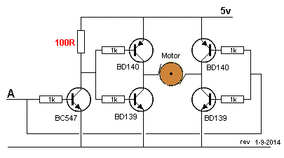
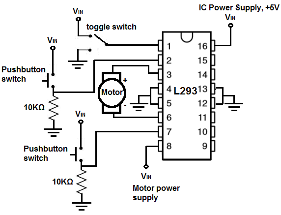
Heres the concept of the h bridge. Such circuit arrangement is known as h bridge because it looks like letter h h bridge circuits are most widely used in dc motor drivers. That is an h bridge allows a microcontroller logic chip or remote control to electronically command the motor to go forward reverse brake and coast. But in this design i think that i will have to use another driver circuit like l298 motor driver ic since above transistors needs higher base currents and as they are in terms of amperes. These circuits are often used in robotics and other applications to allow dc motors to run forwards or backwards. An h bridge is a circuit that is used primarily to control motors.
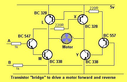
An h bridge is an arrangement of transistors that allows a circuit full control over a standard electric dc motor. For the purposes of this article im focusing on a basic h bridge that is. A h bridge circuit made of tip3055 and tip2955 is used for the motor drive since the motor needs somewhat higher ampere rate. 1 channel iomax 1a built in current limiter current limit mask function. They allow for forward and reverse motion of the motors. How to build an h bridge circuit with transistors.
The motor direction is changed by switching the polarity of the voltage in order to turn the motor one way or the other. Let us see how it gives reverse supply to motor. The ic is optimal for use in driving brushed dc motors for office equipment. The h bridge is a circuit which can drive a dc motor in forward and reverse. How dc motors work. An h bridge is an arrangement of transistors that allow you to control both the direction and speed of the motor.
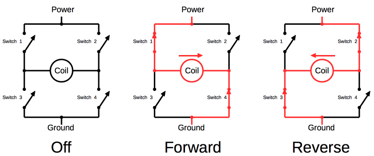
In the circuit diagram we see that the 4 mosfets surrounding the motor form an h shape. Today well examine a very common h bridge module based around the l298n integrated circuit. A more versatile way of controlling a dc motor is to use a circuit called an h bridge. In this circuit we will show how to build an h bridge circuit with transistors. An h bridge is an electronic circuit that switches the polarity of a voltage applied to a load. The mosfets are used as switches and are activated in diagonal pairs.
If sw1 and sw4 are pressed simultaneously then current will flow from ve sw1 a b sw4 gnd. This is easily demonstrated by applying a 9 volt battery to the leads of a small motor and then switching the terminals to change directions. Therefore the motor can be utilized with its full bidirectional capability.
