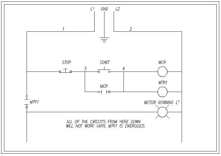
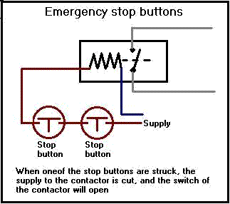
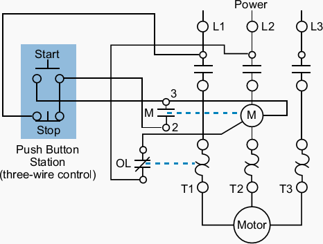
Multiple push button stations. This video builds on the standard 3 wire circuit by incorporating multiple stopstart stations.
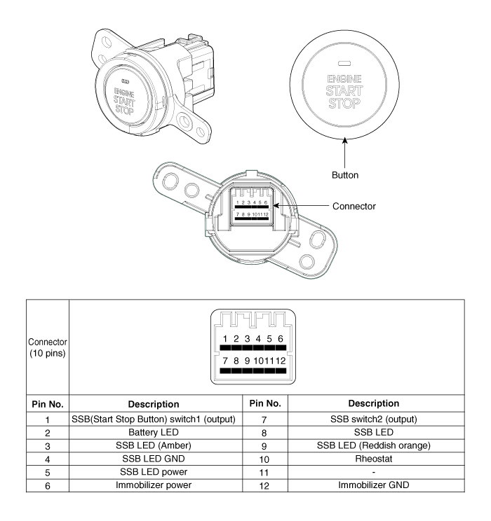
Start Stop Diagram Wiring Diagrams Dat
Start stop electrical diagram. 1 j start 2 3 stop i no. Each part should be placed and connected with other parts in particular way. Start stop switch wiring diagram you will need an extensive skilled and easy to understand wiring diagram. Start stop push button wiring diagram emergency stop push button wiring diagram start stop push button station wiring diagram start stop push button switch wiring diagram every electrical structure consists of various different parts. With the switch closed the control circuit acts as a normal stopstart station controlling a load connected to the pilot device power is sitting on the start and seal in terminals of the pushbutton. Vfd is a short form of variable frequency drive or variable voltage variable frequency drivethe vfds are working based on changing the input frequency and input voltage of the motor we can change the speed of the.
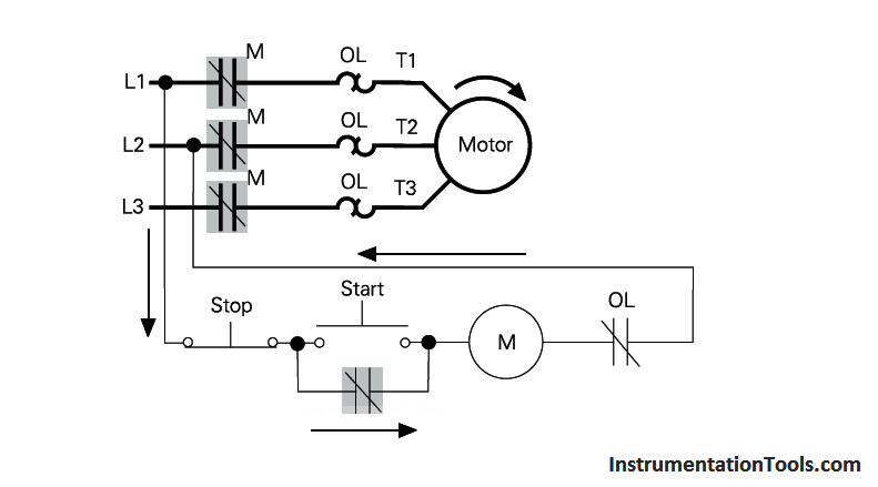
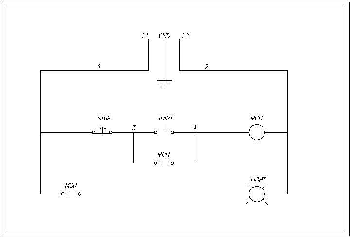
With such an illustrative manual you will be capable of troubleshoot stop and total your projects with ease. Collection of 3 phase contactor wiring diagram start stop. Depressing the stop button breaks the circuit de energizing. Next the start pushbuttons are connected in parallel to form an or logic circuit. Start stop control wiring diagrams single station basic circuit r 1 klai. The most common use of 3 wire control is a startstop control.
Pressing start immediately sends power through the start pushbutton and the seal in contacting energizing the coil. It reveals the elements of the circuit as simplified forms and also the power and signal links between the gadgets. I zl ii i i ii i i fo 0. Otherwise the structure wont function as it ought to be. I operation depressing the start button energizes coil m hold in contacts m and maintains the circuit after the start button is released. Either start pushbuttons can be pressed to energize the coil.
I am here with giving you a vfd start stop wiring diagram for running a vfd through panel board push button and keypad of the vfd it is called hmi. Three wire control multiple stations circuit diagram. This control circuit is a variation of the three wire control circuit. This multiple stopstart circuit in configuration 4 operates as follows. Vfd start stop wiring diagram. A wiring diagram is a simplified traditional pictorial depiction of an electric circuit.
When you press the start button and the stop button is not pressed the 24vdc relay energizes and it pulls in the r1 contactor that feeds three phase power to the motor. See image below for an example of 3 wire control being used to pull in a contactor to start a 3 phase motor. Hgl tech electric 16514 views.
