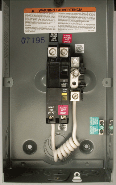
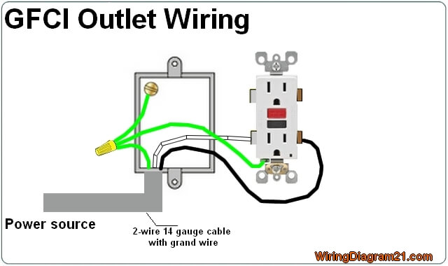
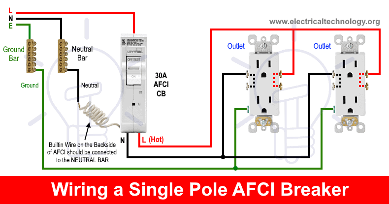
It works by comparing the input current on the ungrounded side red wire to the output current on the neutral side black wire. Ground fault circuit interrupter gfci is a device which secure person from electric shocks from faulty currents in the electrical devices we use in our daily lives.
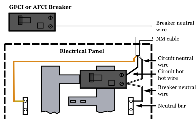
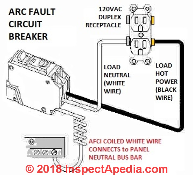
Afci Breaker Wiring Diagram Wiring Diagram Images
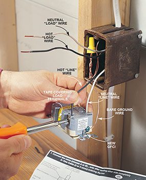
Ground fault circuit interrupter wiring diagram. The ground fault circuit interrupter gfci saves lives. Read on to learn more about proper installation. Gfci as an outlet receptacle combo or circuit breaker automatically cuts off the main power supply within millisecond against electric shock. There are two different kinds for home use electrical outlets and circuit breakers. This is why it is imperative to put the correct wires on the correct screws. If any conductor is not correctly attached to the correct screw the gfci outlet will not work.
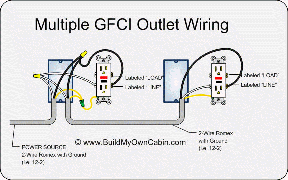
The load terminals on the gfci are not used and the last receptacle is wired directly to the circuit source. A ground fault circuit breaker is properly called a ground fault circuit interrupter breaker or simply a gfci breakerit installs into a homes service panel or breaker box and provides gfci protection for the entire branch circuit it serves. Ground fault circuit interrupters gfcis implement line and load connections to employ an automatic trip action when a difference of electricity is detected. Gfci also known as ground fault circuit interrupter is a protective device which automatically detects the ground faults and leakage current and provides personal protection against electrocution. Gfci outlet wiring diagram. This diagram illustrates the wiring for multiple ground fault circuit interrupter receptacles with an unprotected duplex receptacle at the end of the circuit.
Gfci circuit breakers last longer than gfci outlets and are a good idea if you do not test your gfci outlets on a regular basis.






/electrician-upgrading-a-homes-distribution-board-958969076-5c61c76446e0fb0001dcd5d1.jpg)

