A contactor joins 2 poles together without a common circuit between them while a relay has a common contact that connects to a neutral position. A relay is normally used in appliances below 5kw while a contactor is preferred when the appliance is heavier.

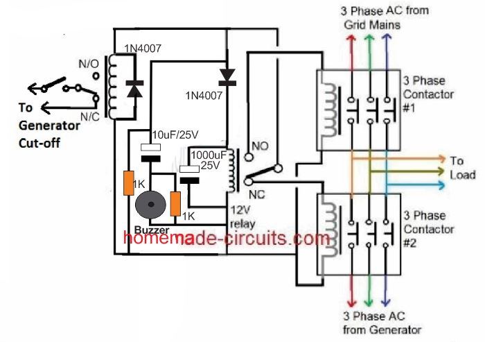
Grid Mains To Generator Changeover Relay Circuit Homemade
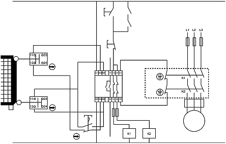
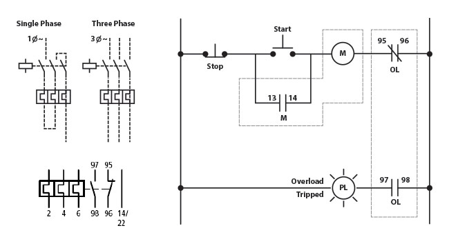
Relay contactor diagram. Contactor vs relay applications. Magnetic contactor circuit diagram luxury thermal overload relay. The diagram symbols in table 1 are used by square d and where applicable conform to nema national electrical manufacturers a ssociation. Its is important to. Contactor wiring diagram pdf download furnas contactor wiring diagram download. 2 days ago i wired 380 to 440 volts contactor for a 3 phase motor and save these images of contactor in pc.
How to wire a contactor. Pdf contactor wiring diagram with timer. Many large pieces of equipment are powered directly from high voltage lines. Contactor wiring and i hope after this post you will be able to wire a 3 phase motor i also published a post about 3 phase motor wiring with magnetic contactor and thermal overload relay but today post and contactor wiring diagram is too simple and easy to learn. Otherwise the arrangement wont function as it. 240 volts ac and 480 volts ac are commonly used for these large pieces of.
These lines far exceed the 120 volts ac standard in most homes. Contactor breakers limit switch no static control standard elementary diagram symbols. A relay is used only in control circuit while a contactor can be used in both control and. Lighting contactor wiring diagram with cell westmagazine net. Contactors are typically built for and used in 3 phase applications where a relay is more commonly used in single phase applications. Difference between contactor and relay since a contactor is required for a higher load a relay is always cheaper than a contactor.
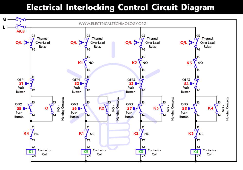
Iec contactor wiring diagram bureaucraticallyfo.


