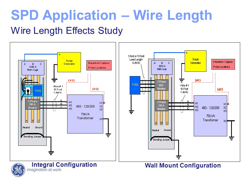
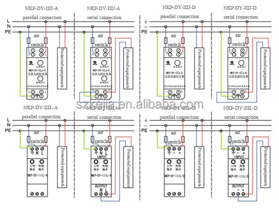
How to fit a type 2 spd remote from the consumer unit with correct conductor lengths. Single phase meter wiring diagram.

Surge Protective Devices Ppt Video Online Download
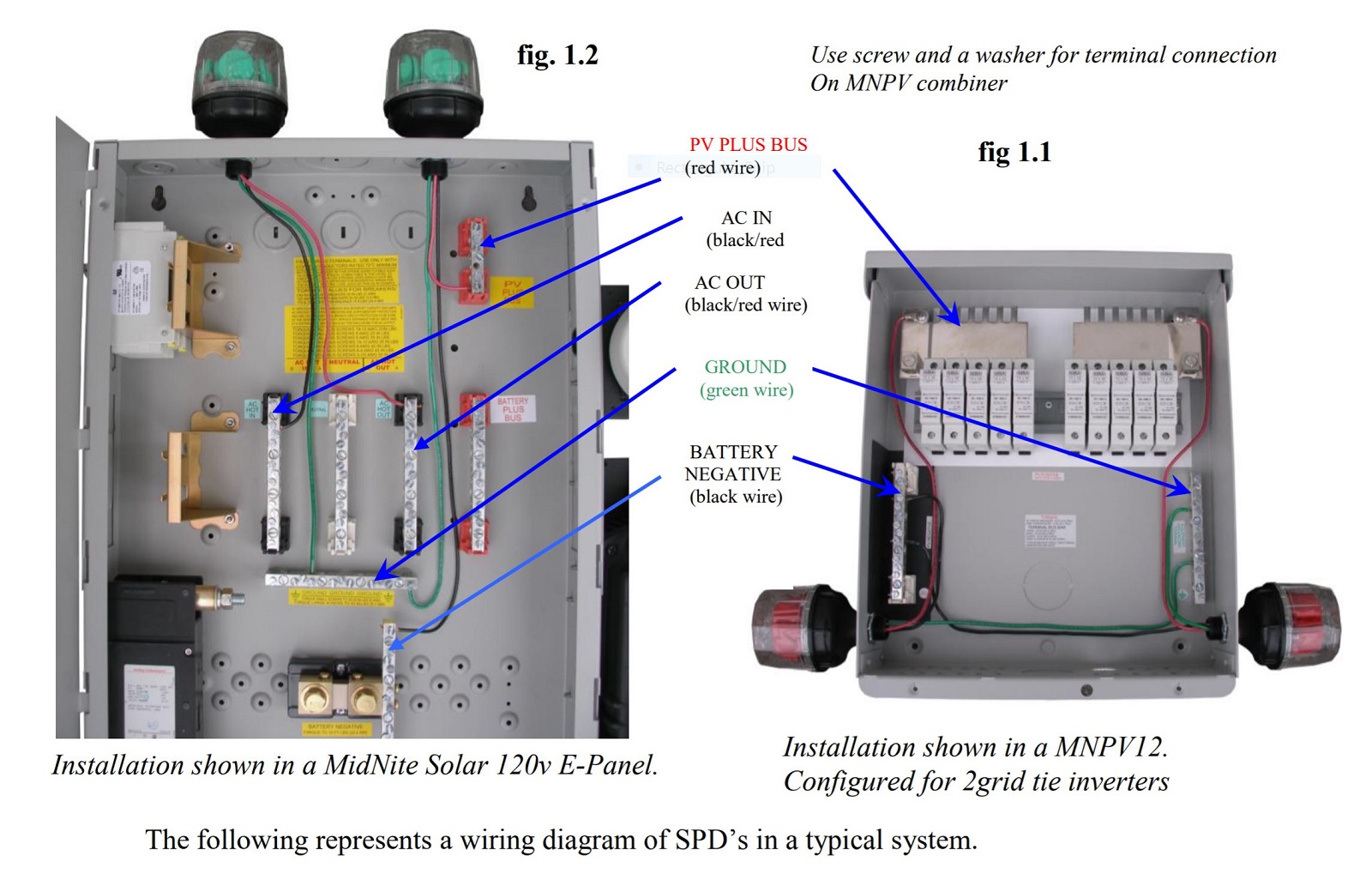
Dc spd wiring diagram. Ct 312c1 36v 650w electric scooter speed controller designed for 36 volt motors up to 650 watts. The conductors used to connect the spd to the line or bus shall not be any longer than necessary and shall avoid unnecessary bends green wire the following represents a wiring diagram of spds in a typical system. You must refer to this diagram while wiring the spd. Maximum current 30 amps. See figures 9 14. Basics 11 mov schematic with block included basics 12 12 208 vac panel diagram.
Apply voltage to spd. Basics 8 aov elementary block diagram. Spd series type 1 and type 2 units do not require over current protection devices fuses or circuit break ers to operate correctly. 36 volt 650 watt. Pv combiners get installed as shown in figure 11 5. Out load as shown in fig.
Both leds in the spd should glow blue as a sign that voltage is present in system spd is connected correctly and working and the system is protected. Select the correct wiring diagram for the spd you are install ing. 12 dc connect the red wire to pv and the black wire to pv or battery minus. Through the enclosure hole and mount the spd enclosure. Basics 9 416 kv pump schematic. Pv plus bus red wire battery negative black wire ground ac in blackred wire ac out blackred wire.
Item spd 36500r wiring directions. Wiring lengths connection options duration. Basics 14 aov schematic with block included basics 15 wiring or connection. Basics 7 416 kv 3 line diagram. Basics 13 valve limit switch legend. 36 volt 250 350 watt electric scootermopedbike brushless dc motor speed controller cw or ccw with optional reverse.
Basics 10 480 v pump schematic. Outback quad dc wiring part 2 pdf 269 kb outback single gvx1448 classic 150 large kit in d3r pdf 214 kb positive ground wiring of classic pdf 220 kb.


